
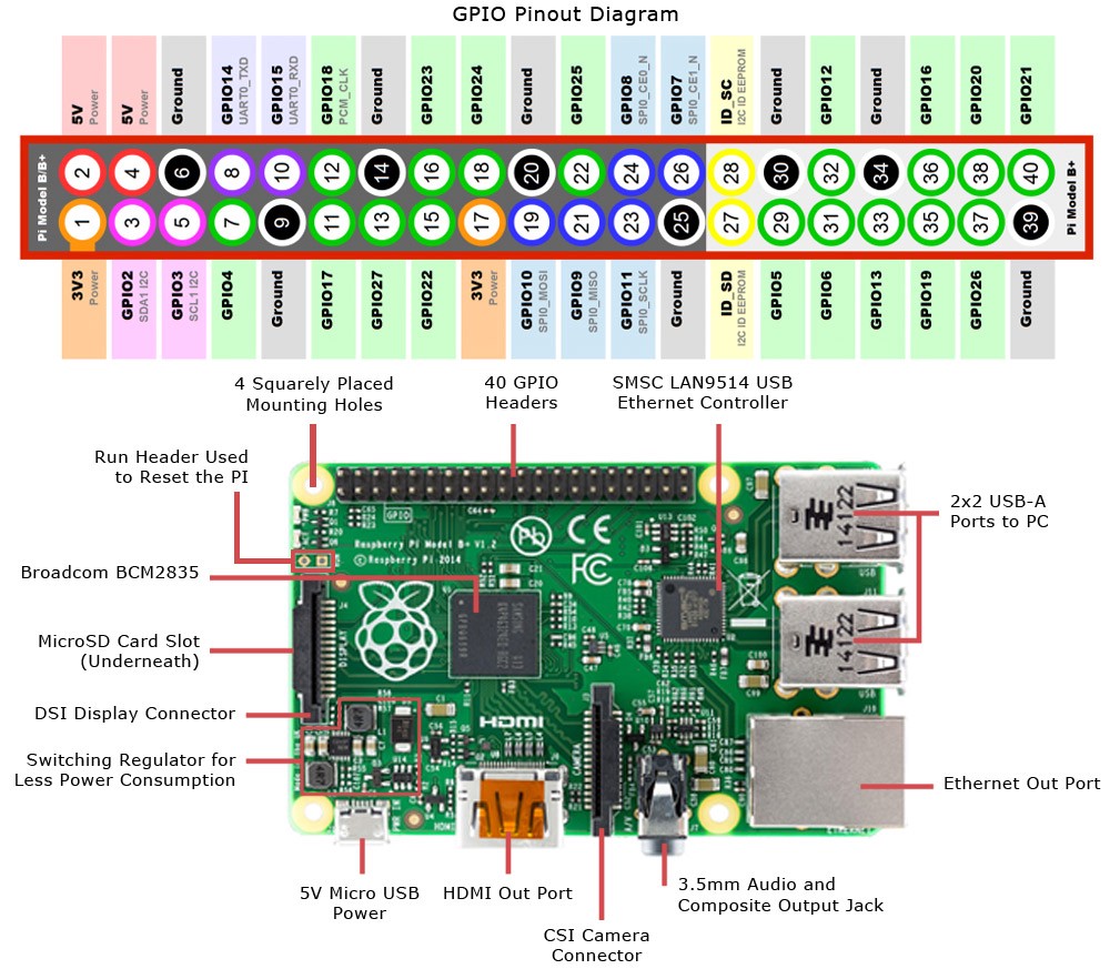
You can not do much of electronics experimenting until you open the gates the GPIO pins on Raspberry Pi. GPIO stands for General Purpose Input Output pins which are 40 in number and present on the top (or bottom if you are holding your pi upside down) of Raspberry Pi. The older model, like older than Pi1 B+ have 26 pins. These pins serves various different purpose like provide ground, provide voltages: 3.3v and 5v and rest serves as GPIO. Though some GPIO pins can also be used for different communication protocols like SPI, I2C, UART similar to pin 0 & 1 in Arduino, which are also used for Serial Communication.
Coming to GPIO pins Usage
Except the power pins all the GPIO pins can be configured as Input or output pins. These pins operate at 3.3V and can only read/write digital signal. Though some pins support PWM which can help you to imitate an analog output signal with digital pin. Also some pins are hardware PWM capable, though the Pi is also able to provide software PWM on all pins through libraries such as pigpio.
Below is an exact count of number of different pins and below is the table of usage of the pins
- 8 ground pins (pin 6, 9, 14, 20, 25, 30, 34, and 39)
- 2 3.3v power (pin 1,7)
- 2 5v power (pin 2,4)
- 26 GPIO pins
- 2 I2C ID EEPROM (reserved for advance use only)
Now coming to some special purposes GPIO pins
- Pin 12, 13, 18, 19 can be used for hardware PWM
- Pin 8 and 10 ae UART pins
- Pins 19, 21, 23, 24, 25 and 26 are used to connect to an SPI device
- Pin 3 and Pin 5 is used for I2C(Inter-Integrated Circuit) communication
- Pin 27 and 28 are also I2C pins for some internal purpose and we don’t mess with them
These GPIO pins can be programmed using various programming languages but we will stick to python, cause its the most widely used language for programming Raspberry Pi.
There are 2 ways in which we can interpret these GPIO pins in our program
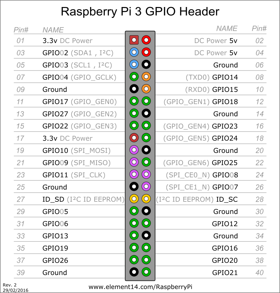
GPIO.setmode(GPIO.BCM)BCM (Broadcom SOC channel) : means that you are referring to the pins by the “Broadcom SOC channel” number, these are the numbers after “GPIO” in above Diagram. But these BCM numbers changed between different version of Raspberry Pi, so its better to use BOARD numbers
GPIO.setmode(GPIO.BOARD)Board : means that you are referring to the pins by the number of the pin the the plug – i.e the numbers printed on the board PIN# in the above diagram.
We will continue to work with these GPIO pins in our subsequent posts.