How ESP8266-01 works : Pinout and Connecting to Arduino

ESP-8266-pinout

EspressIf has been making various IoT chips at an extremely low cost, one such chip is ESP8266. There are various modules of this chip and here we will talk about on such module by Ai-Thinker: ESP8266-01. Also, there are 2 variants of ESP8266-01: blue(512KB flash) and black(1MB flash)

esp8266-01-blue-black

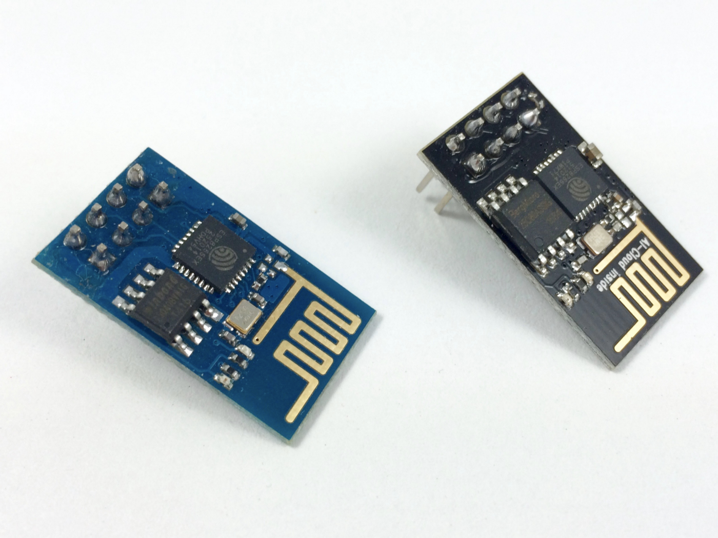
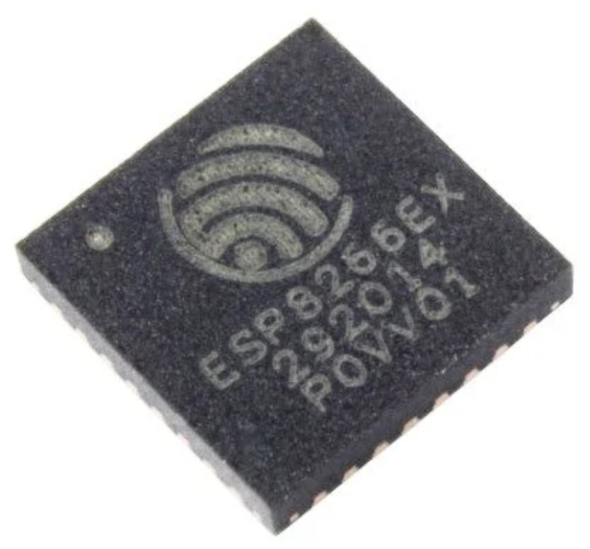
The ESP8266 is a microcontroller chip from Chinese manufacturer Espressif, built around a Tensilica Xtensa LX3 processor, it includes onboard Wi-Fi. Originally intended to be used as UART to WiFi adaptor, allowing other micro-controllers to connect to a Wi-Fi network and make simple TCP/IP connections using Hayes-style (AT) commands, the ESP8266 quickly became popular as a stand-alone micro-controller because of its low price point.

Although the ESP8266 chip is made by Espressif, modules bearing the chip come from a variety of different manufacturers.

ESP8266-01 PIN OUT and Configuration
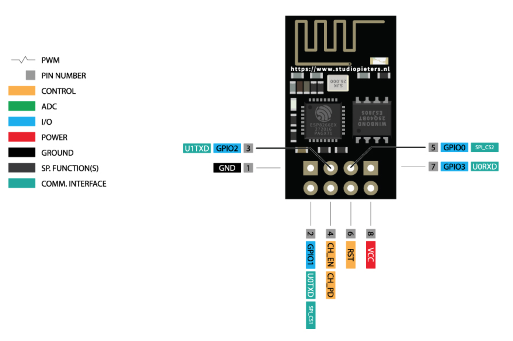
ESP-8266-pinout

Pin Number Pin Name Alternate Name Normally used for Alternate purpose
1 Ground Connected to the ground of the circuit
2 TX GPIO – 1 Connected to Rx pin of programmer/uC  to upload program Can act as a General purpose Input/output pin when not used as TX
3 GPIO-2 General purpose Input/output pin
4 CH_EN Chip Enable – Active high
5 GPIO – 0 Flash General purpose Input/output pin Takes module into serial programming when held low during start up
6 Reset Resets the module
7 RX GPIO – 3 General purpose Input/output pin Can act as a General purpose Input/output pin when not used as RX
8 Vcc Connect to +3.3V only

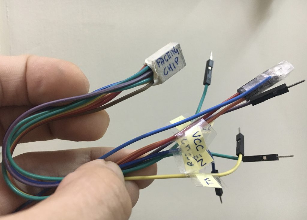
Also, I always prefer to make a guided jumper wires connector for easy working with ESP module.

esp-jumper-connector

Make connection with Arduino

Esp8266-01 comes with AT-commands default firmware there are 2 ways we can interact with that firmware via Arduino.

List of important AT commands.

1.Using Arduino as Host MCU to communicate with ESP8266

Using the Software Serial library we can send serial commands to Arduino and Arduino with again send it to ESP8266 and vice versa. Code Below

#include <SoftwareSerial.h>

SoftwareSerial mySerial(10, 11); // RX, TX

void setup() {
// Open serial communications and wait for port to open:
Serial.begin(57600);
while (!Serial) {
; // wait for serial port to connect. Needed for native USB port only
}

Serial.println(“Goodnight moon!”);

// set the data rate for the SoftwareSerial port
mySerial.begin(4800);
mySerial.println(“Hello, world?”);
}

void loop() { // run over and over
if (mySerial.available()) {
Serial.write(mySerial.read());
}
if (Serial.available()) {
mySerial.write(Serial.read());
}
}


2. Using Arduino As USB-TTL by bypassing ATmega MCU

Arduino can be used as a USB-TTL converter and we can directly send out commands to ESP8266.

Click here to learn how to use Arduino as USB-TTL converter.

What are ESP32, ESP8266 Modules and Development Board

ESP32_chip_ic

One of the major factors which contributed towards the massive explosion of IoT devices in our day to day life is cheap Silicon. There are so many silicon manufactures that are providing highly capable MCU’s for fraction of the cost. One such manufacturer is EspressIf which makes 2 very famous chips with networking capabilities: ESP8266 & ESP32 (photos below).

ESP8266EX-Chip-ICESP32_chip_ic


Mind you, these chips are embedded onto the modules with which most people are familiar. Have a look at the ESP32 module below. These modules go on top of the IoT PCB which we design. Moreover, these modules can be used as MCU+Network_IC (Hostless) or as Network_IC and external MCU (Hosted).

esp32-wroom-32-module


Also, there are Development boards/kits available in the market (image below) which are used to prototyping and learning about these boards. They provide an easy development environment and various debugging features which helps to come up with the binary code(firmware), which goes onto the ESP Module.

ESP32-developer-kit

ESP 8266 Specifications

  • Tensilica Xtensa LX106 32 bit RISC CPU running at 80 MHz
  • On-board Wi-Fi (2.4 GHz)
  • Integrated 10 bit analog to digital converter
  • SDIO 2.0, (H) SPI, UART, I2C, I2S, IR Remote Control, PWM, GPIO
  • 16 GPIO Pins
  • UART – 2x TX and 1x RX
  • Operating Voltage : 3.0 ~ 3.6V
  • Average Operating Current: 80mA
  • Operating Temperature : -40°C ~ 125°C
  • Frequency Range : 2400 ~ 2483.5MHz

ESP 32 Specifications

  • Tensilica Xtensa LX6 microprocessor @ 160 or 240 MHz
  • On-Board Wi-Fi and Bluetooth
  • ADCs, DACs, I²C, UART, CAN 2.0, SPI, I²S, RMII, PWM

Head onto this amazing article on Difference b/w ESP32 & ESP8266

AT Commands for ESP8266: Where and How to use them

At_COMMAND

The Hayes command set or AT commands are instructions used to control a modem, but the default firmware of ESP8266 also allows us to use AT commands to communicate with ESP8266.

AT is the abbreviation of Attention. Every command line starts with “AT” or “at”. Note that the starting “AT” is the prefix that informs the modem about the start of a command line. It is not part of the AT command name. For example, +GMR is the actual AT command name in AT+GMR. However, some people and web sites use them interchangeably as the name of an AT command.

At_COMMAND

Here is a list of AT commands which you can use to communicate with ESP8266 (you can send these commands via Arduino/MCU to drive ESP8266). There are two types of AT commands – basic commands(commands that do not start with “+”) and extended commands(commands that start with “+”).

Basic commands are AT commands that do not start with “+”. For example, D (Dial), A (Answer), H (Hook control) and O (Return to online data state) are basic commands. Rest are extended commands explained below :

Commands Description Set/Execute Parameters
AT+RST restart the module
AT+CWMODE wifi mode AT+CWMODE=<mode> 1= Sta, 2= AP, 3=both
AT+CWJAP join the AP AT+ CWJAP =<ssid>,< pwd > ssid = ssid, pwd = wifi password
AT+CWLAP list the AP AT+CWLAP
AT+CWQAP quit the AP AT+CWQAP
AT+ CWSAP set the parameters of AP AT+ CWSAP= <ssid>,<pwd>,<chl>, <ecn> ssid, pwd, chl = channel, ecn = encryption
AT+ CIPSTATUS get the connection status AT+ CIPSTATUS
AT+CIPSTART set up TCP or UDP connection 1)single connection (+CIPMUX=0) AT+CIPSTART= <type>,<addr>,<port>; 2) multiple connection (+CIPMUX=1) AT+CIPSTART= <id><type>,<addr>, <port> id = 0-4, type = TCP/UDP, addr = IP address, port= port
AT+CIPSEND send data 1)single connection(+CIPMUX=0) AT+CIPSEND=<length>; 2) multiple connection (+CIPMUX=1) AT+CIPSEND= <id>,<length>
AT+CIPCLOSE close TCP or UDP connection AT+CIPCLOSE=<id> or AT+CIPCLOSE
AT+CIFSR Get IP address AT+CIFSR
AT+ CIPMUX set mutiple connection AT+ CIPMUX=<mode> 0 for single connection 1 for mutiple connection
AT+ CIPSERVER set as server AT+ CIPSERVER= <mode>[,<port> ] mode 0 to close server mode, mode 1 to open; port = port
+IPD received data

A brief list of AT commands can be found HERE

Comprehensive list of AT commands can be found HERE