What are ESP32, ESP8266 Modules and Development Board

ESP32_chip_ic

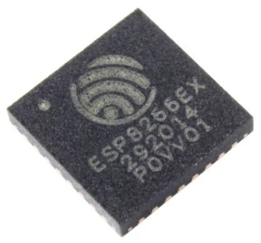
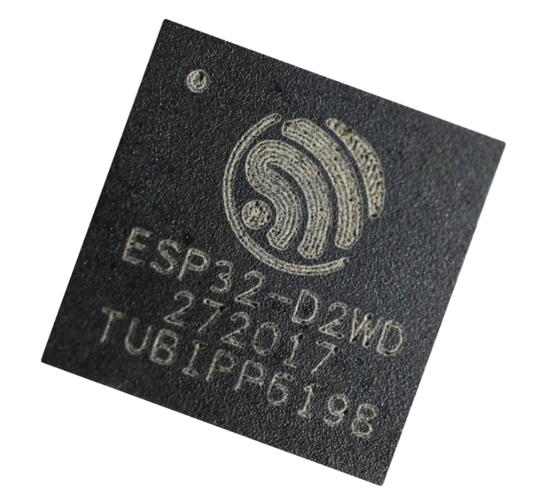
One of the major factors which contributed towards the massive explosion of IoT devices in our day to day life is cheap Silicon. There are so many silicon manufactures that are providing highly capable MCU’s for fraction of the cost. One such manufacturer is EspressIf which makes 2 very famous chips with networking capabilities: ESP8266 & ESP32 (photos below).

ESP8266EX-Chip-ICESP32_chip_ic


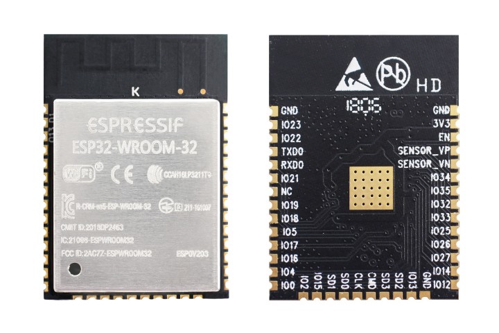
Mind you, these chips are embedded onto the modules with which most people are familiar. Have a look at the ESP32 module below. These modules go on top of the IoT PCB which we design. Moreover, these modules can be used as MCU+Network_IC (Hostless) or as Network_IC and external MCU (Hosted).

esp32-wroom-32-module


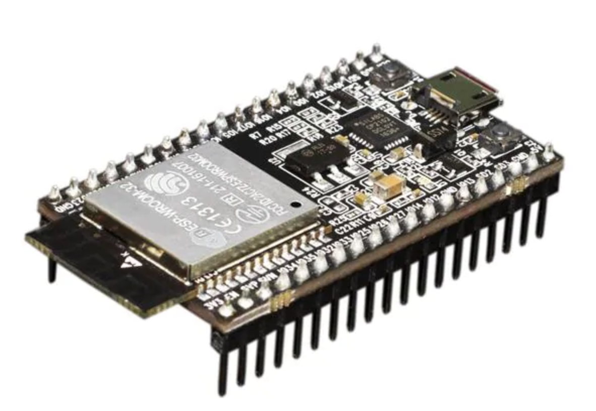
Also, there are Development boards/kits available in the market (image below) which are used to prototyping and learning about these boards. They provide an easy development environment and various debugging features which helps to come up with the binary code(firmware), which goes onto the ESP Module.

ESP32-developer-kit

ESP 8266 Specifications

  • Tensilica Xtensa LX106 32 bit RISC CPU running at 80 MHz
  • On-board Wi-Fi (2.4 GHz)
  • Integrated 10 bit analog to digital converter
  • SDIO 2.0, (H) SPI, UART, I2C, I2S, IR Remote Control, PWM, GPIO
  • 16 GPIO Pins
  • UART – 2x TX and 1x RX
  • Operating Voltage : 3.0 ~ 3.6V
  • Average Operating Current: 80mA
  • Operating Temperature : -40°C ~ 125°C
  • Frequency Range : 2400 ~ 2483.5MHz

ESP 32 Specifications

  • Tensilica Xtensa LX6 microprocessor @ 160 or 240 MHz
  • On-Board Wi-Fi and Bluetooth
  • ADCs, DACs, I²C, UART, CAN 2.0, SPI, I²S, RMII, PWM

Head onto this amazing article on Difference b/w ESP32 & ESP8266

Anatomy Of Internet Of Things : Hardware & Services

internet of things green linked image

Internet of Things is a buzzword these days in the IT sector. With all new devices and services introduced everyday and big players of IT industry like Google and Apple launching there IOT devices, it looks like its going to be a big breakthrough in the world.

internet of things green linked image

Though many people are aware of the concept of Internet of Things but certainly they don’t have enough knowledge regarding the hardware and software used.

Here at Weock we have dissected the concept of IOT in a way so that all the scattered pieces in the mind of our audience are joined together.

The Hardware Squad

The hardware squad make up the visible section of your project. It consists of all the sensor, boards and communications devices.

A. IOT Devices

These devices make up the mainframe of you IOT project

1. Embedded System Boards

The embedded system boards are the brain of your project in which your program will run. You might even have one of these boards with you

  • Arduino
  • Raspberry Pi
  • Intel Galileo
  • Gadgeteer
  • Beaglebone
  • Cubieboard
  • Electric Imp
raspberry pi iot
Raspberry Pi

2. Wearables

These are the devices which can be worn on your body and they will collect data and give information. If you are not a hardware freak then you can buy one of these wearables and start writing programs.

  • Google Glass
  • Samsung Gear 2
  • Pebble Watch
  • Misfit Shine
  • Android Wear
samsung galaxy gear 2
Samsung Galaxy Gear 2

B. Sensors and Actuators

Sensors and Actuators are the devices which collect data and act on the environment.

(we will be explaining each of these devices very soon)


1. Sensors

Sensors collect data from environment and give the data to microcontroller for processing

  • Temperature Sensor (eg. DHT11)
  • Light (eg. LDR, IR)
  • Radio (eg. RF and FM)
  • PIR motion Sensor
  • Ultrasonic Sensor (eg. HC-SR04)
  • Air Quality Sensor
pir-sensor
PIR Sensor

2. Actuators

Actuator are electronics devices which act on the environment based on instructions given by micro-controller

  • Servo Motor
  • Gear Motor

3. Display

Used to display necessary information

  • TFT
  • 7 segment display
  • LED
  • LCD display

4. Relay and Switches

Used to turn devices ON/OFF

C. Smart Devices (connectivity)

These are modules which help in establishing communication between various devices

  • GPSgsm module iot
  • GSM
  • BLE
  • WIFI
  • GPRS
  • RFID
  • NFC


The Platform and Services Squad

These are the technologies which are currently being used in the field of Internet Of Things.

  1. RIOTifttt-logo
  2. Carriots
  3. Lithouse
  4. Sensinode
  5. IFTTT (if this than that)
  6. Arrayent
  7. Alljoyn
  8. ioBridge

Congratulations, if you read the whole article then you have successfully dissected the giant know as Internet Of Things. These are all the concepts which make up the IOT.

If you like our article then Share US among your friends and please give your suggestions and feedback.

Arduino Onboard embedded LED’s Their Function and Color

arduino onboard led

Mounting up of LED directly on the board helps in reducing the cost when done on large scale. Onboard LED’s also looks good when placed on a small board. On Arduino there are 4 onboard LED’s which helps in giving status to the user. In the image below you can observe where these LED’s are located on Arduino.

Click here to Check Specs Of Arduino Uno

arduino onboard led

Name and Function Of Arduino LED’s

So there are 4 LED on Arduino of different color from which 3 are located nearby and one is little far away. Lets Look and Study each Led

arduino status L and power led ON board

1. Power LED (Green)
It is a basic LED which power ON when the device is connected to a power supply (USB or Adapter). It is green in color and shows that arduino is powered ON.

2. Status LED (Orange)
It is a built-in LED connected to digital pin 13. When the pin is HIGH value, the LED is on, when the pin is LOW, it’s off. It is Orange in color. It is also used to make basic LED blinking Example.

3. Serial Communication LED’s (Orange)
Serial communication LED’s are basically communication LED which are powered on when the board sends or receives any data from computer through USB cable.

– TX : When arduino sends data to PC ( eg. sending information )
– RX : When arduino receives data from PC ( eg. downloading program )

Normally there are only 4 LED on Arduino Uno R3 but it may vary depending on the version of the board. The arduino like boards may have a normal 3mm LED placed on them. These onboard LED are very important for a user as he can see the status of his board and what is happening at a particular instance of time.

Arduino Uno R3 Specifications And Parts Name Labbled on Board

Arduino Uno Labelling

Arduino Uno R3 is the most popular project board under the Arduino name.
It is most widely used board and also have tonnes of support and projects available on the internet.
Here is the specification of the arduino board use ATmega 328 microcontroller.

Click here to know Basics of Arduino

Arduino Uno Labelling

Arduino Uno R3 Specifications

Microcontroller                                                     ATmega328
Operating Voltage                                                5V
Input Voltage (recommended)                             7-12V
Input Voltage (limits)                                            6-20V
Digital I/O Pins                                                     14 (of which 6 provide PWM output)
Analog Input Pins                                                 6
DC Current per I/O Pin                                        40 mA
DC Current for 3.3V Pin                                      50 mA
Flash Memory                                                      32 KB (ATmega328)
SRAM                                                                  2 KB (ATmega328)
EEPROM                                                             1 KB (ATmega328)
Clock Speed                                                        16 MHz
Length                                                                  68.6 mm
Width                                                                    53.4 mm
Weight                                                                  25 g

The maximum length and width of the Uno PCB are 2.7 and 2.1 inches respectively, with the USB connector and power jack extending beyond the former dimension. Four screw holes allow the board to be attached to a surface or case. Note that the distance between digital pins 7 and 8 is 160 mil (0.16″), not an even multiple of the 100 mil spacing of the other pins.