Anatomy Of Internet Of Things : Hardware & Services

internet of things green linked image

Internet of Things is a buzzword these days in the IT sector. With all new devices and services introduced everyday and big players of IT industry like Google and Apple launching there IOT devices, it looks like its going to be a big breakthrough in the world.

internet of things green linked image

Though many people are aware of the concept of Internet of Things but certainly they don’t have enough knowledge regarding the hardware and software used.

Here at Weock we have dissected the concept of IOT in a way so that all the scattered pieces in the mind of our audience are joined together.

The Hardware Squad

The hardware squad make up the visible section of your project. It consists of all the sensor, boards and communications devices.

A. IOT Devices

These devices make up the mainframe of you IOT project

1. Embedded System Boards

The embedded system boards are the brain of your project in which your program will run. You might even have one of these boards with you

  • Arduino
  • Raspberry Pi
  • Intel Galileo
  • Gadgeteer
  • Beaglebone
  • Cubieboard
  • Electric Imp
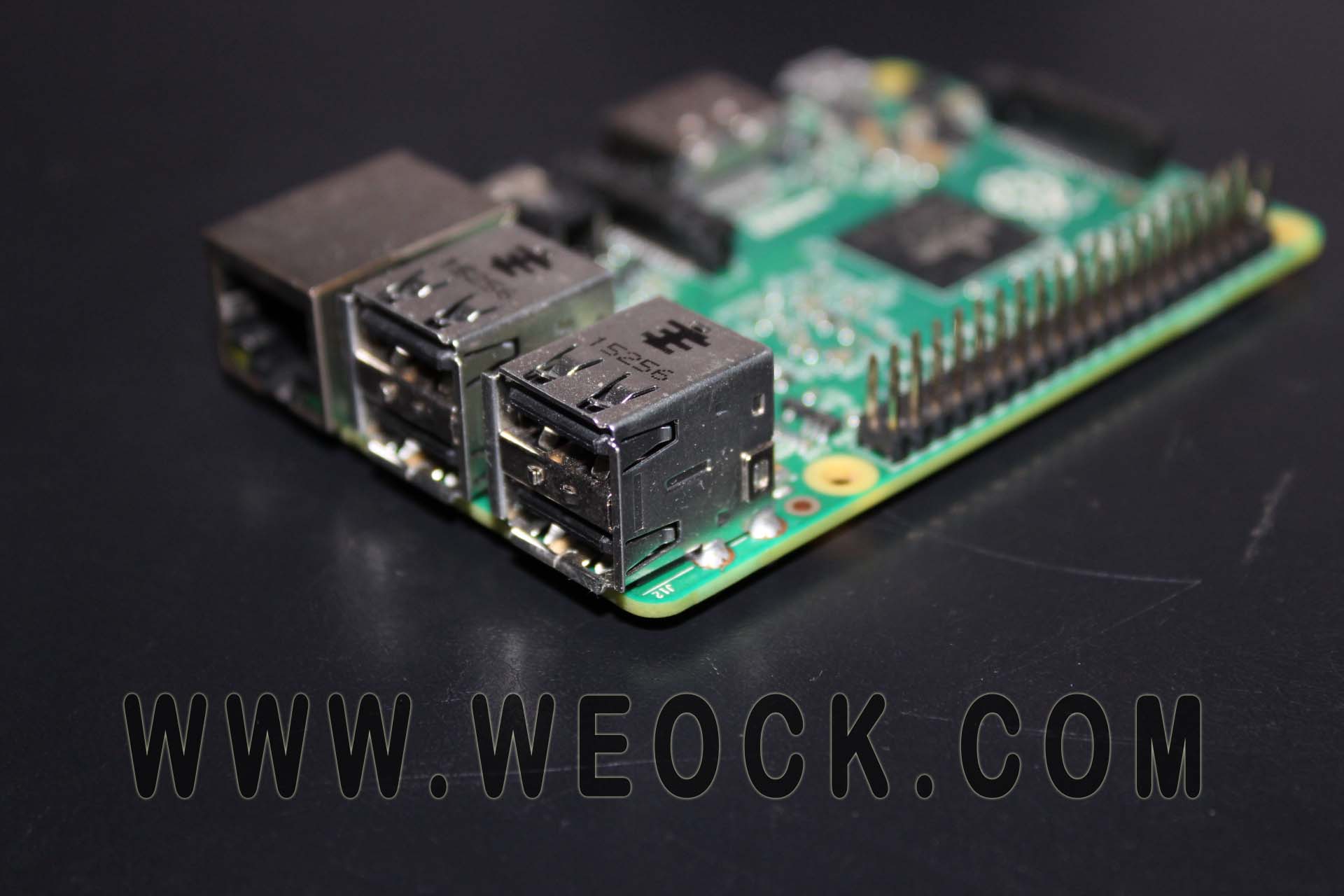
raspberry pi iot
Raspberry Pi

2. Wearables

These are the devices which can be worn on your body and they will collect data and give information. If you are not a hardware freak then you can buy one of these wearables and start writing programs.

  • Google Glass
  • Samsung Gear 2
  • Pebble Watch
  • Misfit Shine
  • Android Wear
samsung galaxy gear 2
Samsung Galaxy Gear 2

B. Sensors and Actuators

Sensors and Actuators are the devices which collect data and act on the environment.

(we will be explaining each of these devices very soon)


1. Sensors

Sensors collect data from environment and give the data to microcontroller for processing

  • Temperature Sensor (eg. DHT11)
  • Light (eg. LDR, IR)
  • Radio (eg. RF and FM)
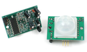
  • PIR motion Sensor
  • Ultrasonic Sensor (eg. HC-SR04)
  • Air Quality Sensor
pir-sensor
PIR Sensor

2. Actuators

Actuator are electronics devices which act on the environment based on instructions given by micro-controller

  • Servo Motor
  • Gear Motor

3. Display

Used to display necessary information

  • TFT
  • 7 segment display
  • LED
  • LCD display

4. Relay and Switches

Used to turn devices ON/OFF

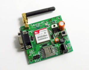
C. Smart Devices (connectivity)

These are modules which help in establishing communication between various devices

  • GPSgsm module iot
  • GSM
  • BLE
  • WIFI
  • GPRS
  • RFID
  • NFC


The Platform and Services Squad

These are the technologies which are currently being used in the field of Internet Of Things.

  1. RIOTifttt-logo
  2. Carriots
  3. Lithouse
  4. Sensinode
  5. IFTTT (if this than that)
  6. Arrayent
  7. Alljoyn
  8. ioBridge

Congratulations, if you read the whole article then you have successfully dissected the giant know as Internet Of Things. These are all the concepts which make up the IOT.

If you like our article then Share US among your friends and please give your suggestions and feedback.


How to Install NOOBS on Raspberry Pi

raspberry pi usb ports image

To start with Raspberry Pi you need an OS (operating system) to run on it like all personal computers. On this OS you will run all you programs and applications.

Like on your laptop you can install various OS – like Windows, Ubuntu etc. Similarly on your Raspberry Pi you can install various operating system.

raspberry pi logo

Check the list of Operating System Available for Raspberry PI

NOOBS stands for New Out Of the Box Operating system. NOOBS is an easy operating system installer which contains Raspbian. It also provides a selection of alternative operating systems which are then downloaded from the internet and installed.

Steps to Install NOOBS on SD Card

Buy an SD card 

Card capacity should be 8GB or more, preferably class-10 or more

Download Noobs

Click HERE and download the version of noobs (if you are unsure choose the option with Offline and Network install and Download Zip)

Prepare The Sd Card

Format your sd card with the tool given HERE (choose either for windows or Mac)

Insert your SD card into the computer or laptop’s SD card reader and make a note of the drive letter allocated to it, e.g. G:/

You will need to set “FORMAT SIZE ADJUSTMENT” option to “ON” in the “Options” menu to ensure that the entire SD card volume is formatted, and not just a single partition. After that click Format

DRAG AND DROP NOOBS FILES

Once your SD card has been formatted, drag all the files in the extracted NOOBS folder and drop them onto the SD card drive.
The necessary files will then be transferred to your SD card.
When this process has finished, safely remove the SD card and insert it into your Raspberry Pi.

FIRST BOOT

Plug in your keyboard, mouse, and monitor cables.
Now plug the USB power cable into your Pi.
Your Raspberry Pi will boot, and a window will appear with a list of different operating systems(you will only get raspbian based on your download) that you can install. We recommend that you use Raspbian – tick the box next to Raspbian and click on Install.
Raspbian will then run through its installation process. Note that this can take a while.

Congratulations, Now you have successfully installed. After this the Rasoberry Pi will restart and load into its graphical interface.

An Introduction to Functions in Arduino | How to Make Funciton

Arduino hd image

An Arduino function is a block of code that has a name and a block of statements that are executed when the function is called. The functions void setup() and void loop() have already been discussed here.

Arduino hd image

Custom functions can be written to perform repetitive tasks and reduce clutter in a program. Functions are declared by first declaring the function type. This is the type of value to be returned by the function such as ‘int’ for an integer type function. If no value is to be returned the function type would be void. After type, declare the name given to the function and in parenthesis any parameters being passed to the function.

type functionName(parameters)
{
statements;
}

The following integer type function delayValue() is used to set a delay value in a program by reading the value of a potentiometer. It first declares a local variable v, sets v to the value of the potentiometer which gives a number between 0-1023, then divides that value by 4 for a final value between 0-255, and finally returns that value back to the main program.

int delayVal()
{
int v;                               // create temporary variable ‘v’
v  = analogRead(pot);    // read potentiometer value
v /= 4;                            // converts 0-1023 to 0-255
return v;                        // return final value
}

Curly braces
It define the beginning and end of function blocks and statement blocks such as the void loop() function and the for and if statements. type function() {   statements; }

An opening curly brace { must always be followed by a closing curly brace }. This is often referred to as the braces being balanced. Unbalanced braces can often lead to cryptic, impenetrable compiler errors that can sometimes be hard to track down in a large program.

Semicolon
A semicolon must be used to end a statement and separate elements of the program. A semicolon is also used to separate elements in a for loop.

int x = 13;   // declares variable ‘x’ as the integer 13


Block comments, or multi-line comments
These are areas of text ignored by the program and are used for large text descriptions of code or comments that help others understand parts of the program. They begin with /* and end with */ and can span multiple lines.

Single line comments 
They begin with // and end with the next line of code. Like block comments, they are ignored by the program and take no memory space.
Single line comments are often used after a valid statement to provide more information about what the statement accomplishes or to provide a future reminder.

Learn Simple Hello World Program

These are all the basic tools you need to create a function in Arduino.

The setup() and loop() Functions in Arduino Programming

arduino infinity official logo

As we have seen in Basic Structure for Arduino that there are 2 basic functions in an Arduino Program.

arduino infinity official logo

setup()

The setup() function is called once when your program starts. Use it to initialize pin modes, or begin serial. It must be included in a program even if there are no statements to run.

void setup()
{
pinMode(pin, OUTPUT);      // sets the ‘pin’ as output
}

 loop()

After calling the setup() function, the loop() function does precisely what its name suggests, and loops consecutively, allowing the program to change, respond, and control the Arduino board.

void loop()
{
digitalWrite(pin, HIGH);   // turns ‘pin’ on
delay(1000);               // pauses for one second
digitalWrite(pin, LOW);    // turns ‘pin’ off
delay(1000);               // pauses for one second
}

By using these 2 functions you can create any Arduino Program.

Basic Structure of Arduino Programming | Setup & Loop Function

Basic Structure of Arduino Programming | Setup & Loop Function

The basic structure of the Arduino programming language is predefined and fairly simple. It runs in at least two parts. These two required parts, or functions, enclose blocks of statements.

Arduino official Logo

This is Basic Structure of Every Arduino Program

void setup()
{
statements;
}void loop()
{
statements;
}

Where setup() is the preparation, loop() is the execution. Both functions are required for the program to work.

The setup function should follow the declaration of any variables at the very beginning of the program. It is the first function to run in the program, is run only once, and is used to set pinMode or initialize serial communication.

The loop function follows next and includes the code to be executed continuously – reading inputs, triggering outputs, etc. This function is the core of all Arduino programs and does the bulk of the work.

So this is the primitive or basic structure of an Arduino Program.

Arduino Onboard embedded LED’s Their Function and Color

arduino onboard led

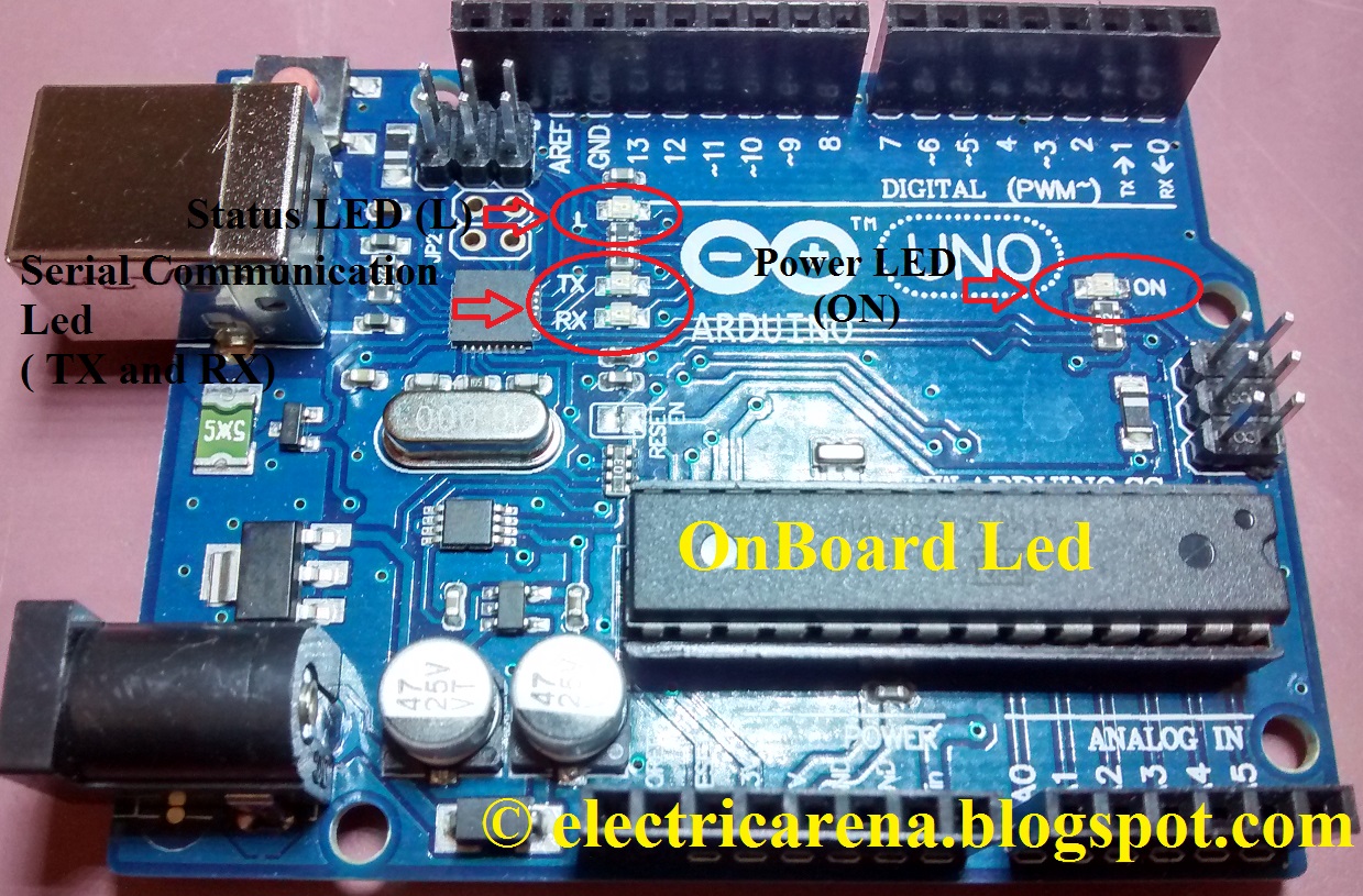
Mounting up of LED directly on the board helps in reducing the cost when done on large scale. Onboard LED’s also looks good when placed on a small board. On Arduino there are 4 onboard LED’s which helps in giving status to the user. In the image below you can observe where these LED’s are located on Arduino.

Click here to Check Specs Of Arduino Uno

arduino onboard led

Name and Function Of Arduino LED’s

So there are 4 LED on Arduino of different color from which 3 are located nearby and one is little far away. Lets Look and Study each Led

arduino status L and power led ON board

1. Power LED (Green)
It is a basic LED which power ON when the device is connected to a power supply (USB or Adapter). It is green in color and shows that arduino is powered ON.

2. Status LED (Orange)
It is a built-in LED connected to digital pin 13. When the pin is HIGH value, the LED is on, when the pin is LOW, it’s off. It is Orange in color. It is also used to make basic LED blinking Example.

3. Serial Communication LED’s (Orange)
Serial communication LED’s are basically communication LED which are powered on when the board sends or receives any data from computer through USB cable.

– TX : When arduino sends data to PC ( eg. sending information )
– RX : When arduino receives data from PC ( eg. downloading program )

Normally there are only 4 LED on Arduino Uno R3 but it may vary depending on the version of the board. The arduino like boards may have a normal 3mm LED placed on them. These onboard LED are very important for a user as he can see the status of his board and what is happening at a particular instance of time.

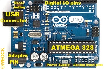
Arduino Uno R3 Specifications And Parts Name Labbled on Board

Arduino Uno Labelling

Arduino Uno R3 is the most popular project board under the Arduino name.
It is most widely used board and also have tonnes of support and projects available on the internet.
Here is the specification of the arduino board use ATmega 328 microcontroller.

Click here to know Basics of Arduino

Arduino Uno Labelling

Arduino Uno R3 Specifications

Microcontroller                                                     ATmega328
Operating Voltage                                                5V
Input Voltage (recommended)                             7-12V
Input Voltage (limits)                                            6-20V
Digital I/O Pins                                                     14 (of which 6 provide PWM output)
Analog Input Pins                                                 6
DC Current per I/O Pin                                        40 mA
DC Current for 3.3V Pin                                      50 mA
Flash Memory                                                      32 KB (ATmega328)
SRAM                                                                  2 KB (ATmega328)
EEPROM                                                             1 KB (ATmega328)
Clock Speed                                                        16 MHz
Length                                                                  68.6 mm
Width                                                                    53.4 mm
Weight                                                                  25 g

The maximum length and width of the Uno PCB are 2.7 and 2.1 inches respectively, with the USB connector and power jack extending beyond the former dimension. Four screw holes allow the board to be attached to a surface or case. Note that the distance between digital pins 7 and 8 is 160 mil (0.16″), not an even multiple of the 100 mil spacing of the other pins.

Arduino: What, Who and How to use it | Learn Arduino Basic

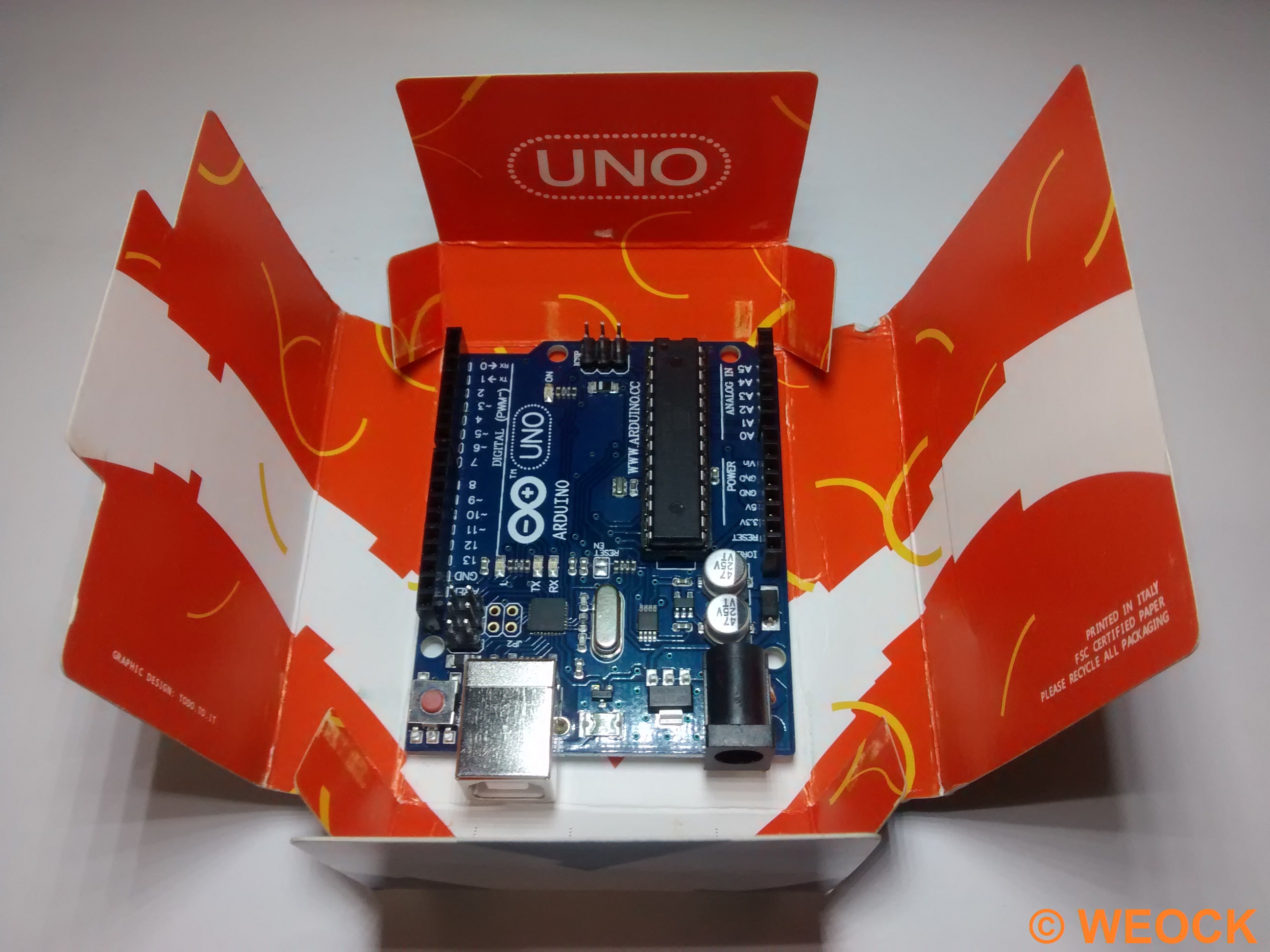
arduino in original box

If you are a electronics hobbyist or if you are from engineering background then you have probably heard about ARDUINO. If yes then well and good and if not then I will tell you about it in the following post……..

arduino in original box

So first question

What is Arduino ?

Arduino is an open-source electronics platform based on easy-to-use hardware and software. It’s intended for anyone making interactive projects.
Basically it is an “open-source” means anyone can use and modify it and sell their own version without taking the permission of original owner.
It is a electronics board which helps you to

Make Your Own Hardware, Run Your Own Program

Who Should Use Arduino ?

Arduino can be used by any one whether a person with electronics as a interest or a enginnering student to make models or some person who wants to interact with its computer using sensors.
Arduino is an inexpensive board which is available for nearly $25 ( 1500) but having endless possibilities.

How to use Arduino ?

Using arduino is no big deal, technically its just like plugging your pendrive and start working with it.
But there are various steps to configure arduino which you can learn by Clicking Here.

arduino plugged into usb cable

So basically Arduino is an open-source microcontroller which you can use to play around and interact with the physical world present around you. So pursue you hobby and happy Arduinoing.