Raspberry Pi GPIO pins [EVERYTHING EXPLAINED]

raspberry-pi-gpio

You can not do much of electronics experimenting until you open the gates the GPIO pins on Raspberry Pi. GPIO stands for General Purpose Input Output pins which are 40 in number and present on the top (or bottom if you are holding your pi upside down) of Raspberry Pi. The older model, like older than Pi1 B+ have 26 pins. These pins serves various different purpose like provide ground, provide voltages: 3.3v and 5v and rest serves as GPIO. Though some GPIO pins can also be used for different communication protocols like SPI, I2C, UART similar to pin 0 & 1 in Arduino, which are also used for Serial Communication.

raspberry-pi-gpio

Coming to GPIO pins Usage

Except the power pins all the GPIO pins can be configured as Input or output pins. These pins operate at 3.3V and can only read/write digital signal. Though some pins support PWM which can help you to imitate an analog output signal with digital pin. Also some pins are hardware PWM capable, though the Pi is also able to provide software PWM on all pins through libraries such as pigpio.

Below is an exact count of number of different pins and below is the table of usage of the pins

  • 8 ground pins (pin 6, 9, 14, 20, 25, 30, 34, and 39)
  • 2 3.3v power (pin 1,7)
  • 2 5v power (pin 2,4)
  • 26 GPIO pins
  • 2 I2C ID EEPROM (reserved for advance use only)

gpio-usage

Now coming to some special purposes GPIO pins

  • Pin 12, 13, 18, 19 can be used for hardware PWM
  • Pin 8 and 10 ae UART pins
  • Pins 19, 21, 23, 24, 25 and 26 are used to connect to an SPI device
  • Pin 3 and Pin 5 is used for I2C(Inter-Integrated Circuit) communication
  • Pin 27 and 28 are also I2C pins for some internal purpose and we don’t mess with them

These GPIO pins can be programmed using various programming languages but we will stick to python, cause its the most widely used language for programming Raspberry Pi.

There are 2 ways in which we can interpret these GPIO pins in our program

GPIO.setmode(GPIO.BCM)

BCM (Broadcom SOC channel) : means that you are referring to the pins by the “Broadcom SOC channel” number, these are the numbers after “GPIO” in above Diagram. But these BCM numbers changed between different version of Raspberry Pi, so its better to use BOARD numbers

GPIO.setmode(GPIO.BOARD)

Board : means that you are referring to the pins by the number of the pin the the plug – i.e the numbers printed on the board PIN# in the above diagram.

We will continue to work with these GPIO pins in our subsequent posts.

RESIN.IO – Update your IOT Devices Remotely

Resin.io is a web server which helps to deploy our code on a variety of Linux devices connected to the platform. You can also monitor, manage and update your fleet of devices from anywhere around the world.

Resin.io can also be regarded as fleet management and remote update solution – DevOps over IOT ; So the idea is to provide tools similar to what developers use in the cloud but to make them adaptable to the embedded scenario.

Moreover, the Switch between the older and the latest version will be extremely fast (no message displaying your software is being updated)

resin.io platform

Resin.io works in 3 basic steps

1. Develop

2. Deploy

3. Manage

Lets dig deeper and find out how these things works

Here is a the DFD(data flow diagram) which shows how Resin.io platform works

resin.io data flow diagram

Docker Container : How to build and basic commands

docker1

In the previous post we read about how to pull and run a container with single RUN command. Here we will see how to build a container from scratch, perform operation on that container and push our container to docker hub.

docker1

Before we dive deeper, we need to understand that container is only runtime instance of a Image. And same image can be used to create multiple containers.Also, Each container is identified with a unique Container ID.

To list all the running containers

sudo docker ps

To list all the containers dead or alive

sudo docker container ls -all

Commands to perform operations on Continers

Docker container is formed when we create a runtime instance of Image. Here is life cycle of a docker contianer

docker-container-life-cycle

Here are all the operations which can be performed on docker container (you can get containerID by using the command – sudo docker container ls -al)

Go inside a Container (attach to a container)

sudo docker attach containerID

Top processes within a container

sudo docker top containerID

Stop a running container

sudo docker stop containerID

Delete a Container

sudo docker rm containerID

Check stats of a container (CPU/mem)

sudo docker stats containerID

Pause processes in running contianer

sudo docker pause containerID

Un-Pause processes in running contianer

sudo docker unpause containerID

Kill processes inside a container

sudo docker kill containerID

Building you own Docker Images

There are tonnes of images available on Docker HUB but you can always create your own image and then push it to docker hub.

Docker images are always created with a file called Dockerfile (D capital). You can have docker file in any directory of your system but your docker file will be stored by docker daemon in your local docker registry.

Editing of Docker file Check Here.

For now we will see how to build a Docker Image with Dockerfile. CD to the directory where your Dockerfile is stored and fire the build command (-t used to tag the image with the name dockerImage)

sudo docker build -t dockerImage

This docker Image will now be stored in our local docker registry (can be checked by – sudo docker images)

Pushing Docker Image to Docker Hub

Now that we have created our image in local registry, we will upload it to the Docker HUB so that it is available on the cloud

First create a account on docker hub and then login to docker hub from your local PC

sudo docker login

There is a notation for all the images present on dockerhub – username/imageName:tag

Now we will tag our image (it will take local image and tag it as Dockerhub image locally)

sudo docker tag dockerImage username/imageName:tag

Finally we will push our image to Dockerhub

sudo push username/imageName:tag

Now if somebody wants to run our image in their system, they just have to execute run command and our docker image will be first pulled and then run into the system

sudo docker run -it username/imageName:tag

That’s all for the basics of docker, the next articles on docker will talk about some advance processes we can do with docker.

Docker : Installation, Pull and Run a Container from Docker HUB

docker-install

Installation of Docker is pretty straightforward. In this article we will be focusing on Linux installation for docker. Do check below links for docker installation in other OS

-Install Docker on Ubuntu

-Install Docker on Windows

-Install Docker on MacOS

-Install Docker on Raspbian (Raspberry PI)

Alternatively, for Linux/Raspberry Pi just run this command and you are good to go

curl -sSL https://get.docker.com | sh

docker-install

Follow the below instructions to install docker on linux machine [OPTIONAL]

1. Add GPG keys for official docker repo

curl -fsSL https://download.docker.com/linux/ubuntu/gpg | sudo apt-key add -

2. Add docker repo to apt sources

sudo add-apt-repository "deb [arch=amd64] https://download.docker.com/linux/ubuntu $(lsb_release -cs) stable"

3. Update package database

sudo apt-get update

4. Install Docker

sudo apt-get install -y docker-ce

Moreover you can check the full installation HERE


Basic Commands to check Docker Installation

Check weather docker is installed and running (to quit CTRL+C)

sudo systemctl status docker

List Docker (list of docker commands, also management command-since docker 2017)

sudo docker

Docker Version (returns the version of client and server (engine/daemon/service)

sudo docker version

Docker Info (returns details about our configuration and setup for our engine)

sudo docker info

Docker Daemon Start/Stop

Docker has 2 components :
1. Docker Daemon (Engine) : This is the core of Docker which runs in the background
2. Docker CLI (Client) : Docker component with which user interacts

docker-cli-daemon

Both these components communicate with each other using REST API’s on Port number – 2376

START Docker Daemon

sudo service docker start

STOP Docker Daemon

sudo service docker stop

Running a Container

Before running a Container we need to have a Docker Image (as container is a runtime instance of docker image), we can not run a container without having a Docker Image , cause that will not make any sense.

So here are some Commands for for Docker Images

View Docker Images present on our computer

sudo docker images
sudo docker images ls

View details of Docker Image present

sudo docker inspect ImageID

Delete Docker image from System

sudo docker rmi ImageID

So now that we know about docker images lets see how to run them, and no worries if you don’t have any image in you system (we have that covered)


Docker RUN command

Here is the most important docker command which is used to Run Images and if that image is not present locally on you system then docker run will download it from dockerhub and run it

sudo docker run -it Image

We can attach additional parameter as -d (for detach mode) , -p (to map port of docker and host)

To give it a try, run ubuntu image (if its not present locally, which i guess not, then it will download and run that command)

sudo docker run centos –it /bin/bash

This command will download the centOS image from docker hub and start an interactive session at /bin/bash

Alternatively, if you want only to pull image and not run it, you can use the below command. Also this command can also be used when your local system has a outdated image and you want to update you local copy with updated copy.

sudo docker pull centos

Thats all for this session, in next tutorial we will explore more into containers.

Docker Overview : Architecture and Terms (Image, Container, HUB)

docker-build-ship-run

Docker is a container management service which helps to Build-Ship-Run our software anywhere. In simple terms Docker aggregates all the dependencies and files of our software into a single container, which is then treated as an independent unit and can be shipped and run anywhere. Also, Docker containers are platform and OS independent.

docker-build-ship-run

If you ever read about docker, you must be knowing how it is advantageous over using Virtual Machines, but there are many other benefits of using docker :-

  1. Docker containers are allocated resources(CPU, Memory, Storage) dynamically based on their usage; unlike VM’s in which we have to pre-allocate all the resources.
  2. Reduced startup time as docker runs on top our host OS – saves boot-up time.
  3. We can have multiple instances of programs within a single container, or have multiple containers which can communicate with each other.
  4. Provides a consistent computing environment throughout the whole SDLC (dev,qa,prod)

Here is an image which explains how Docker is different from VM’s

vm-vs-docker

Both Docker Container and VM requires an Infrastructure(hardware) and Host Operating System. Unlike Docker, Virtual Machines require another software called hypervisor -which helps to run Guest OS on top of Host OS- which require additional hardware resources and most of the functionalities of the guest OS are never used by our apps.

Whereas, Docker Containers – which are package of our app and its dependencies – just require a Docker Daemon which runs over our Host OS and is very light weight. Wait! whats docker daemon, hmm let us first go through all the terms which we will come across while working with Docker


Important terms related to Docker

  • Docker Engine (Docker Daemon) : Docker engine is a part of docker which runs Docker container. And Daemon is just a computer program that runs as a background process, rather than being under the direct control of an interactive user. So Docker engine/ Docker Daemon runs in background and we run our containers on top of it.
  • Docker Container : A Docker container is a live running instance of a Docker image. A container is a standard unit of software that packages up code and all its dependencies so the application runs quickly and reliably from one computing environment to another.
  • Docker Image : A Docker Image is the template (application plus required binaries, libraries, env variables and config files) needed to build a running Docker Container (the running instance of that image).
  • Docker HUB : Docker hub is a repository on cloud for all your docker images (like github for code). It host pre-build images of famous software’s like wordpress, Ubuntu, centOS etc. You can also push your images to docker hub which can be used by anyone.

That’s all for this tutorial, in next tutorial we will dive into some technicalities and see how to install docker and how to pull and run a container.

DFD and Code

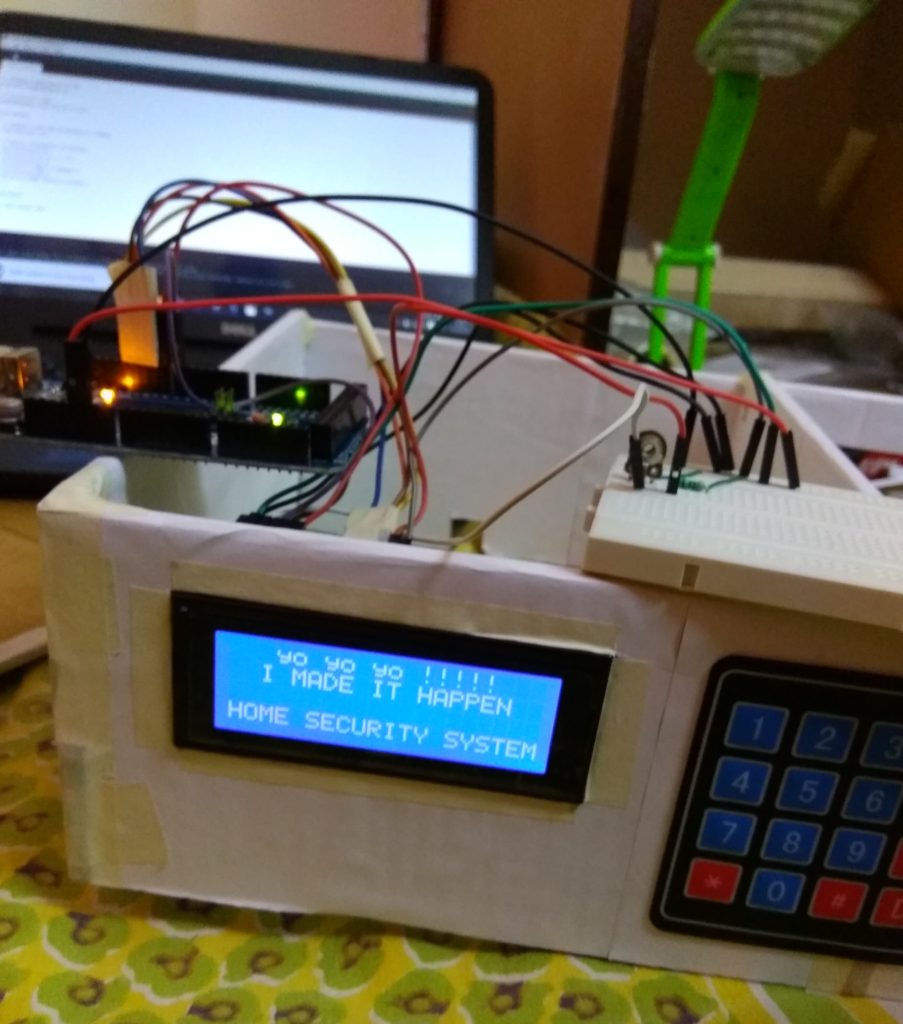
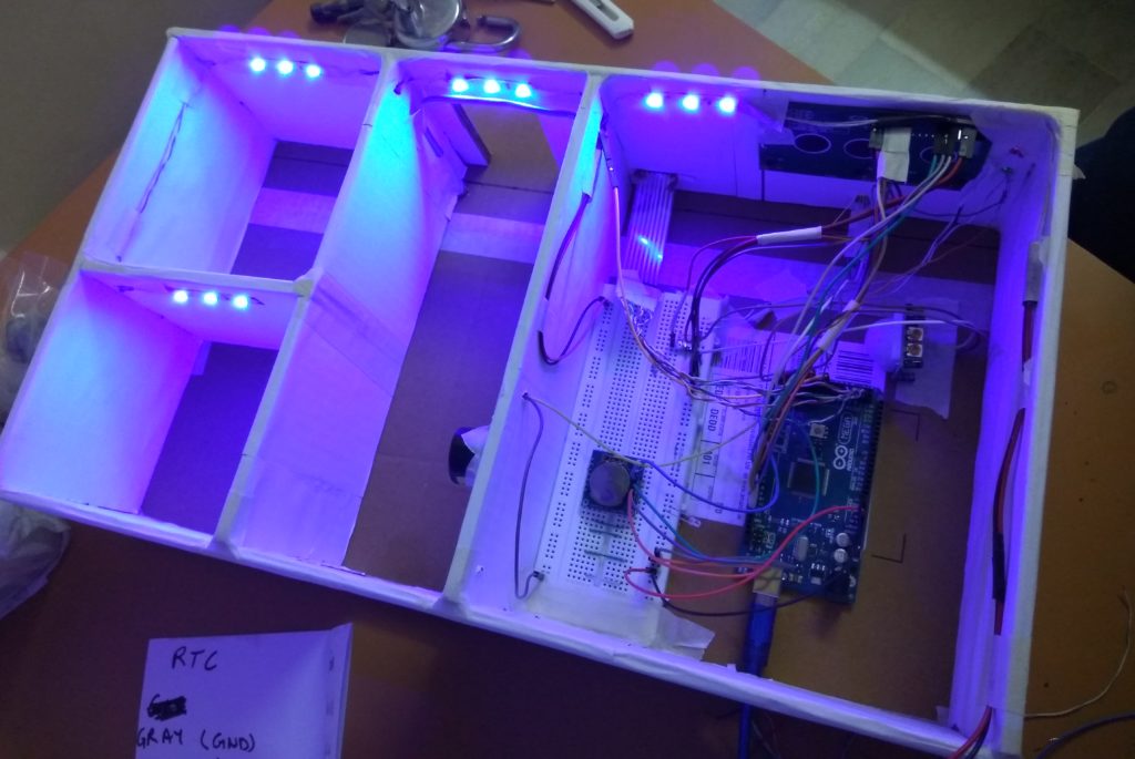
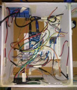
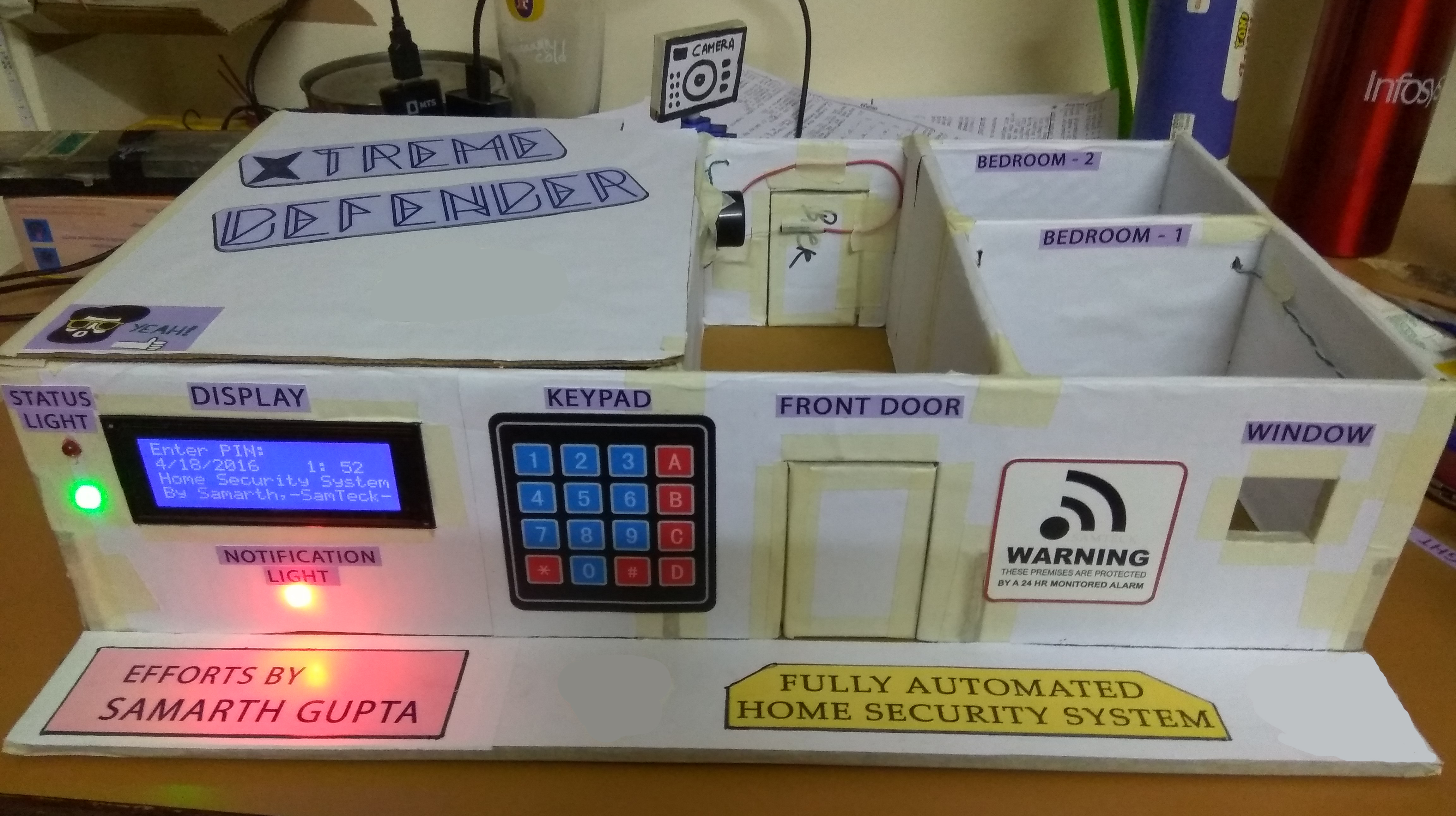
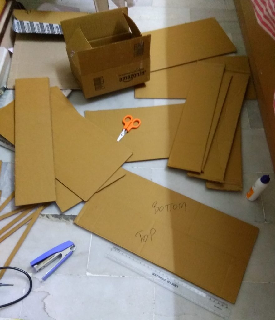
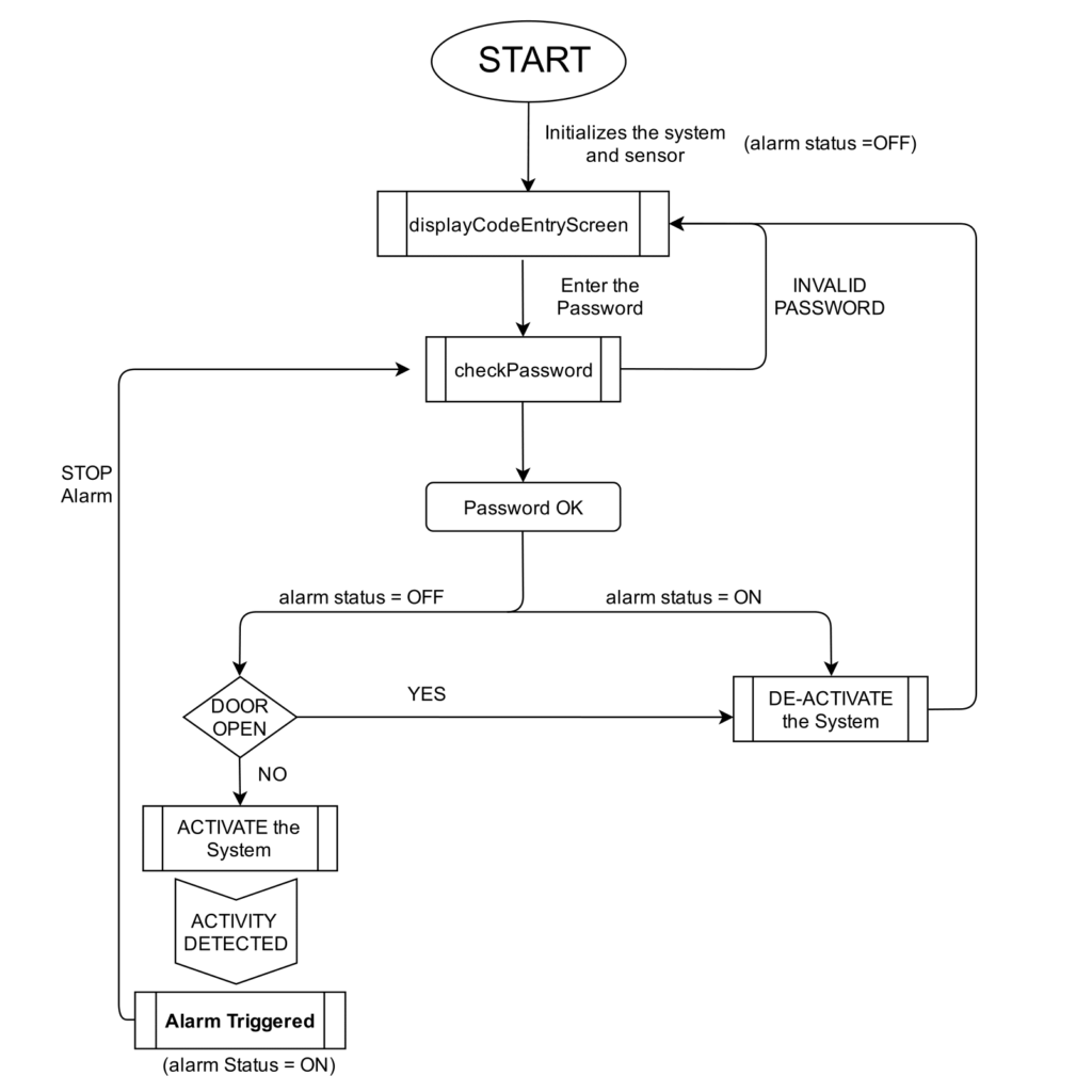
Here is the process flow of the Xtreme Defender

DFD xtreme defender process flow


And here is the full code of this project (arduino sketch)

/*
 * Copyright (C) 2016 Samarth Gupta
 * Project Title: Xtreme Defender - Home Security System
 * Author: Samarth Gupta
 * Started Date: 15/4/16
 * Project Sponsored by - www.samteck.net
 * Version: 1.0
 */

/////////////////////////////////////////////////////////////////////////
#include<LiquidCrystal.h>
#include<Wire.h>
#include<Password.h>
#include<Keypad.h>
#include<Servo.h>
#include "RTClib.h"

//-----Declaring Global Variables-----//

//Keypad
Password password = Password("1234"); //Delared the password for system

const byte ROWS = 4; //Delared the number of rows in keypad
const byte COLS = 4; //Delared the number of colums in keypad

char keys[ROWS][COLS] = { {'1','2','3','A'},  //telling the arduino about the keys of keypad
                          {'4','5','6','B'},
                          {'7','8','9','C'},
                          {'*','0','#','D'} };

byte rowPins[ROWS] = {46,47,48,49}; //Rows pins connection to Arduino
byte colPins[COLS] = {50,51,52,53}; //Columns pins connection to Arduino

Keypad keypad = Keypad(makeKeymap(keys),rowPins,colPins,ROWS,COLS); //Making the keypad object

//Servo
Servo myservo;
int pos = 90; //initial position of servo at Right angle

//Real time Clock
RTC_DS1307 RTC;

//LCD Display
LiquidCrystal lcd(7,8,9,10,11,12); //Assigning the various pins of LCD to Arduino
int passwd_pos = 15;  //password position on the LCD

//Notifications LED
int redPin = 29;  //connect red pin of LED to pin no. 29 on arduino
int bluePin = 31; //connect blue pin of LED to pin no. 31 on arduino
int ledDelay = 50;//delay the led time by 50ms

//Staus Light
int greenLED = 37;  //connect green LED to pin no. 37 on arduino
int redLED = 38;    //connect red LED to pin no. 38 on arduino

//PIR Sensors
int pirPin1 = 39; //connect pir 1 to pin no 39 in arduino
int pirPin2 = 34; //connect pir 2 to pin no 34 in arduino

//Door Switches
int door1 = 41; //door 1 switch is connected to pin no 41 on arduino
int door2 = 42; //door 2 switch is connected to pin no 42 on arduino

//Speaker
int speakerPin = 35;  //alaram speaker is connected to pin no 35;

//Blue anbient light Relay connection
int relay = 4;  //Connect pin 4 of arduino to realy board

//Other variables
int alarmStatus = 0;  //setting these variables to 0
int zone = 0;
int alarmActive = 0;

//-----Beginning setup Function-----//

void setup(){
  Serial.begin(9600); //send data to computer via serial communication at 9600bps
  lcd.begin(20, 4);   //Telling the size of the LCD by samteck
  Wire.begin();       //Setting up I2C communication with Arduino
  RTC.begin();        //Start getting time form RTC module
  RTC.adjust(DateTime(__DATE__,__TIME__));//Set the time on RTC to compile time

  myservo.attach(2);  // attaches the servo on pin 2 to the servo object
  myservo.write(pos);

  //setting up pin  modes of LED Lights
  pinMode(redPin,OUTPUT);
  pinMode(bluePin,OUTPUT);
  pinMode(redLED,OUTPUT);
  pinMode(greenLED,OUTPUT);

  pinMode(speakerPin,OUTPUT);

  pinMode(relay,OUTPUT);

  //setting pinmode of sensors and switches
  pinMode(pirPin1,INPUT);  //Bedroom 1
  pinMode(pirPin2,INPUT);  //Garage
  pinMode(door1,INPUT); //Front door
  pinMode(door2,INPUT); //Back door

  digitalWrite(redLED,LOW);
  digitalWrite(greenLED,HIGH);
  digitalWrite(speakerPin,LOW);

  digitalWrite(relay,HIGH);

  digitalWrite(pirPin1,LOW);
  digitalWrite(pirPin2,LOW);

  calibration();    //call the calibration function to PIR initialization
  
  displayCodeEntryScreen(); //display the starting screen

  keypad.addEventListener(keypadEvent); //add an event listener for this keypad
  }

//-----Beginning loop Function-----//

void loop(){
  DateTime now = RTC.now();   //take current time and date from RTC module

  digitalWrite(redPin,HIGH);
  digitalWrite(bluePin,HIGH);

  //Setting the date and time
  lcd.setCursor(0,1);
  lcd.print(now.day(),DEC);
  lcd.print('/');
  lcd.print(now.month(),DEC);
  lcd.print('/');
  lcd.print(now.year(),DEC);
  lcd.print(' ');

  lcd.setCursor(13,1);
  lcd.print(now.hour(),DEC);
  lcd.print(':');
  lcd.setCursor(16,1);
  lcd.print(now.minute(),DEC);

  keypad.getKey();    //get key press from keypad

  if(alarmActive==1){
    if(digitalRead(pirPin1)==HIGH)
    {
      zone=0;
      alarmTriggered();
    }
    if(digitalRead(door2)==LOW)
    {
      zone=1;
      alarmTriggered();
    }
    if(digitalRead(door1)==LOW)
    {
      zone=2;
      alarmTriggered();
    }
    if(digitalRead(pirPin2)==HIGH)
    {
      zone=3;
      alarmTriggered();
    }
  }
}
  
//////////////  Here comes Functions  ////////////////

void keypadEvent(KeypadEvent eKey){
  switch(keypad.getState()){
      case PRESSED:
        if(passwd_pos - 15 >=5){
            return;
        }
        lcd.setCursor((passwd_pos++),0);
        switch(eKey){
          case '#':
            passwd_pos=15;
            checkPassword();
            break;
            
          case '*':
            password.reset();
            passwd_pos=15;
            break;

           default:
            password.append(eKey);
            lcd.print("*");
         }  
  }
}

void checkPassword(){     //to check if correct pin is entered or not
  if(password.evaluate()){
    if(alarmActive==0 && alarmStatus==0){
      activate();
      }
    else if(alarmActive==1 || alarmStatus==1){
      deactivate();
      }  
  }
    else{
      invalidCode();
      }
}

void activate(){ //to activate the system if correct pin is entered
  if((digitalRead(door1)==HIGH) && (digitalRead(door2)==HIGH)){
    digitalWrite(redLED,HIGH);
    digitalWrite(greenLED,LOW);
    digitalWrite(2,HIGH);
    lcd.setCursor(0,0);
    lcd.print("SYSTEM ACTIVE !!!!!");
    alarmActive=1;
    password.reset();
    delay(2000);
    }
   else{
    if(digitalRead(door1)==LOW && digitalRead(door2)==LOW){
    lcd.clear();
    lcd.setCursor(0,1);
    lcd.print(" BOTH Door Open ");
    lcd.setCursor(0,2);
    lcd.print("Close & Reactivate");
    }
    else if(digitalRead(door1)==LOW){
    lcd.clear();
    lcd.setCursor(0,1);
    lcd.print(" FRONT Door Open ");
    lcd.setCursor(0,2);
    lcd.print("Close & Reactivate");
    }
    else{
    lcd.clear();
    lcd.setCursor(0,1);
    lcd.print(" BACK Door Open ");
    lcd.setCursor(0,2);
    lcd.print("Close & Reactivate");
    }
    delay(2000);
      deactivate();   //if door are open then system will not activate
    } 
}

void deactivate(){    // to deacivate the system
  alarmStatus=0;
  digitalWrite(redLED,LOW);
  digitalWrite(greenLED,HIGH);
  lcd.clear();
  lcd.setCursor(0,0);
  lcd.print(" SYSTEM DEACTIVATED!");
  digitalWrite(speakerPin,LOW);
  alarmActive=0;
  password.reset();
  delay(5000);
  digitalWrite(relay,HIGH);

  displayCodeEntryScreen();   //basically restarts the system
  }

void displayCodeEntryScreen(){    //show up the first screen on the boot
  lcd.clear();
  lcd.setCursor(0,0);
  lcd.print("Enter PIN:");
  lcd.setCursor(0,2);
  lcd.print("Home Security System");
  lcd.setCursor(0,3);
  lcd.print("By Samarth,-SamTeck-");
}

void invalidCode(){  //display when invalid code is entered
  password.reset();
  lcd.clear();
  lcd.setCursor(1,0);
  lcd.print("INVALID CODE! LOL!");
  lcd.setCursor(5,2);
  lcd.print("TRY AGAIN!");
  digitalWrite(greenLED,LOW);
  digitalWrite(redLED,HIGH);
  delay(2000);
  digitalWrite(redLED,LOW);
  delay(1000);
  displayCodeEntryScreen();
}

void alarmTriggered(){    //this function is called whenever input is received on any of the sensor
  int expected_pos;
  int incr;
  digitalWrite(speakerPin,HIGH);
  digitalWrite(relay,LOW);
  digitalWrite(redPin,HIGH);
  digitalWrite(bluePin,LOW);

  password.reset();
  alarmStatus=1;
  lcd.clear();
  lcd.setCursor(0,2);
  lcd.print("  SYSTEM TRIGGERED  ");
  lcd.setCursor(0,4);
  if(zone==0)
  {
    expected_pos=95;
    lcd.print("Motion in Bedroom 1 ");
    delay(1000);  
  }
  else if(zone==1)
  {
    expected_pos=60;
    lcd.print("  Back Door Open");
    delay(1000);  
  }
  else if(zone==2)
  {
    expected_pos=70;
    lcd.print("  Front Door Open");
    delay(1000);  
  }
  else if(zone==3)
  {
    expected_pos=10;
    lcd.print(" Motion in Garage ");
    delay(1000);  
  }

  //setting up position for Servo motor

  if(expected_pos > pos)
    incr=1;
  else
    incr=-1;

  for(pos=pos; pos != expected_pos; pos += incr)
  {
    myservo.write(pos);
    delay(5);  
  }

  StrokeLight();
}

void StrokeLight(){                    //Stroke LED Lights
    digitalWrite(redPin, HIGH);        // turn the red light on
    delay(ledDelay); // wait 50 ms
    digitalWrite(redPin, LOW);         // turn the red light off
    delay(ledDelay); // wait 50 ms
    digitalWrite(redPin, HIGH);        // turn the red light on
    delay(ledDelay); // wait 50 ms
    digitalWrite(redPin, LOW);         // turn the red light off
    delay(ledDelay); // wait 50 ms
    digitalWrite(redPin, HIGH);        // turn the red light on
    delay(ledDelay); // wait 50 ms
    digitalWrite(redPin, LOW);         // turn the red light off
    delay(ledDelay); // wait 50 ms
    delay(10); // delay midpoint by 100ms
    digitalWrite(bluePin, HIGH);       // turn the blue light on
    delay(ledDelay); // wait 50 ms
    digitalWrite(bluePin, LOW);        // turn the blue light off
    delay(ledDelay); // wait 50 ms
    digitalWrite(bluePin, HIGH);       // turn the blue light on
    delay(ledDelay); // wait 50 ms
    digitalWrite(bluePin, LOW);        // turn the blue light off
    delay(ledDelay); // wait 50 ms
    digitalWrite(bluePin, HIGH);       // turn the blue light on
    delay(ledDelay); // wait 50 ms
    digitalWrite(bluePin, LOW);        // turn the blue light off
    delay(ledDelay); // wait 50 ms
    }          

void calibration(){
  int i=0;
  lcd.clear();
  lcd.setCursor(5,0);
  lcd.print("WELCOME TO");
  lcd.setCursor(0,1);
  lcd.print("Xtreme Defender 666");
  lcd.setCursor(0,2);
  lcd.print(" A Fully Automated ");
  lcd.setCursor(0,3);
  lcd.print("Home Security System");  
  delay(5000);
  lcd.clear();
  lcd.setCursor(0,0);
  lcd.print("LOADING BOOTSTRAP");
  lcd.setCursor(0,1);
  for(i=0;i<20;i++){
      lcd.print(".");
      delay(150);
  }
  lcd.setCursor(0,2);
  lcd.print("LOADING NCC. FILES");
  lcd.setCursor(0,3);
  for(i=0;i<20;i++){
      lcd.print(".");
      delay(100);
  }
  delay(1000);
  
  for(i=0;i<=100;i++){
    lcd.clear();
    lcd.setCursor(0,0);
    lcd.print("Initializing .......");
    lcd.setCursor(0,1);
    lcd.print("PIR Sensors");
    lcd.setCursor(0,2);
    lcd.print(i);
    lcd.print("%");
    delay(50);
  }
  lcd.setCursor(8,2);
  lcd.print("--OK DONE--");
  delay(500);
  lcd.setCursor(0,3);
  lcd.print("LOADING START SCREEN");
  delay(1500);
}


Glimpse of the Project

Here are some interesting photos of Xtreme Defender


The Base is ready

house looking strucyre


Added LCD and Keypad

lcd-keypad


Making some connections and deploying RTC

making connections and rtc


Added LED strips connected to a Relay Module (12V) to add extra embellishment to the house

led strips installed


With all the electronics diffusing into each other, Have a look

wires scattered in the project


Now everything is done time to decorate the house

xtreme defender in light xtreme defender in dark

This is it guys, in the coming posts, we will be discussing technicalities of the project. Cheers

Xtreme Defender – Setting up the Structure for the Project

So, I started my project with planning and setting up the base for my home (which will be protected eventually). The main motto was to use the recyclable material as much possible. Also, I wanted the structure to be super strong which can bear the periodic wear and tear which will occur in making the Project. Moreover, the House should at least look similar to the general concept of a modern house.

Got great help from a friend studying Architecture (shoutout for) – Tusshar Bhan

So, I began with an Amazon Box (something like below)

amazon box


I did some planning for the structure of project with resources on the internet and knowledge of my own. Afterwards, I came up with the basic layout of the house and start cutting the box into suitable pieces with proper dimensions.

cutting the box into peices


Now, the next thing was to keep in mind the embellishment of the structure so that it is soothing to the eyes. Therefore I wrapped it with the white sheets which will continue to act a wallpaper for the walls.

structure covered with white sheets


Afterwards, the walls were ready and the necessary cut was made for the doors and windows. Plus I also made some cuts at the intersection of the walls to give an extra Stability to the overall structure.

walls made and structure blueprint


Now, the walls were erected and random cardboard board pieces were transformed into an (at least) house looking structure.

house looking structure

So, guys, this was the first step towards the making of the Xtreme-Defender, Home Security System.

Do check out the next section of the project.

Configure Python in Eclipse with Pydev – Download and Install

In these tutorials, we will be learning Python, so that we can use it to make great IoT projects, instead of using python shell, I will recommend you guys to configure an IDE so that your programming is much faster and efficient.

Here we will learn how to Download-Install-Configure PYTHON with eclipse and start using the environment for programming.

Installing Python

python insatallation

Firstly, we will download and install Python on our Machine aka PC –

https://www.python.org/downloads/   – Download the latest version of Python (don’t download the legacy[older] version) and start with the normal installation process.

During Installation check ‘Next’ a bunch of times but do remember to tick the checkbox – add as an environment variable. If you forget to tick that box check out This Article 

Now that we are done with the installation, we will confirm if python is correctly installed or not by typing ‘python‘ on the terminal

C:\Users\Samarth Gupta>python
Python 3.6.4 (v3.6.4:d48eceb, Dec 19 2017, 06:04:45) [MSC v.1900 32 bit (Intel)] on win32
Type "help", "copyright", "credits" or "license" for more information.
>>>

This confirms that python is successfully installed on your machine.

Installing Eclipse

eclipse inatallation

Now we will download the Eclipse as out IDE – https://www.eclipse.org/downloads/

As of writing this post Eclipse Oxygen was the latest version. During installation configure it as a JAVA environment.

Installing and Configuring Pydev

Ohh yes, we just clicked a few buttons and now we have both Python and Eclipse installed, now its time to unite them with a plugin called ‘Pydev’

Open Eclipse -> Help -> Eclipse Marketplace

pydev-installation

Now search for Pydev and click install


After installation, we will create a new Python Project with the help of pydev

Follow the below Steps

  1. Click – File -> New -> Other (choose pydev project)choose pydev project
  2. Now Configure the project as below and click Finishpyhton project specs
  3. That was easy – our project is ready, now we will create our first python file (right-click the project -> New -> File and give it some name with extension ‘.py’).
  4. Edit the python file as below and click ‘Run’ (just hit next to whatever alert comes in your way)
    print('batman is here')
  5. Now you can see in Console the output is printedpython-program

From now on we will be writing all our code in these .py files and output will be printed in the console window.

That was all with the configuration need for our python projects. Now just dive into the programming with python in our coming tutorials.

Google’s UriBeacon : What it is & How it Works Explained

uribeacon- the physical web

Google’s UriBeacon is a project under their Physical Web initiative whose main aim is DIGITAL to PHYSCAL convergence. The UriBeacon project was launched in 2014 to explore how to use BLE technology to share URLs. The UriBeacon protocol uses BLE to transmit a basic URL or short weblink that can be detected by nearby mobile devices. This ‘link’ can then drive a user to a web page that corresponds to content associated with that beacon.

uribeacon- the physical web

Moreover you do not need a specialized app to read that link, all you need is a UriBeacon browser which can read that URL (more and more browser will add this feature with the time). There will be 2 options in the browser to identify a UriBeacon

  • Automatic Mode – Whenever your smartphone enters in the proximity of a beacon the URL link will be notified.
  • Manual Mode – In manual mode you need to search every time you want to scan a beacon.

uribeacon with mobile app

The benefit with this approach is that one app(browser) intended to detect UriBeacons can serve all beacons regardless of what brand, or owner they are associated with.

The potential of the Physical Web Concept is huge as cost of entry and time to deploy is a couple of order of magnitude lower as compared to other technologies.

These search results could provide a jumping off point to a wealth of information, media and rich interactive content in the same way the Google results page does today. So in a nutshell these UriBeacon act as a Physical Web showing results of the locale on your mobile phone.