
We know that ESP8266-01 is an impressive, low cost and powerful module with networking capabilities. But sometimes it becomes a bit tedious task to flash your firmware onto it. So to simplify the whole process and understanding of putting your firmware on ESP8266-01 (by AI-Thinker), we are writing this article.
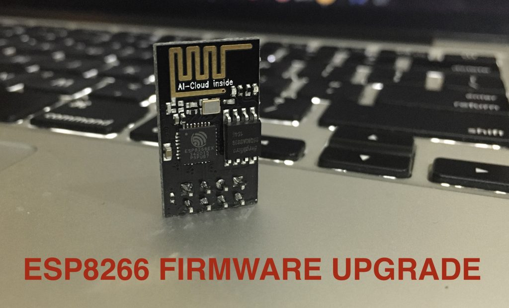
The AI-Thinker boards have a black PCB with the words “AI-CloudInside” printed near the PCB antenna. These have a flash memory of 1 Megabyte (aka 8 megabits). The other type by the generic manufacturers might just have 512 KiB flash (and their PCBs could be blue in color).
ESP8266 comes pre-programmed with an AT command set firmware, meaning, you can simply hook this up to your Arduino device and get about as much WiFi-ability as a WiFi Shield offers. This module has a powerful on-board processing and storage capability that allows it to be integrated with the sensors and other applications through its GPIOs.
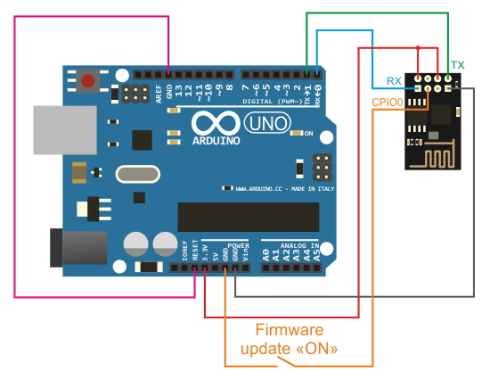
Hardware Setup
We need below-mentioned hardware components:
- ESP8266 (obvious, but still needs a mention)
- USB-TTL (learn how to use Arduino as USB-TTL adapter)
- Bunch of jumper wires
To put ESP8266 into bootloader mode we need to first pull GPIO-0 to GND. When we restart the module, this setup will put it into bootloader mode.
Software Setup
There are 2 ways to flash your firmware, the First one is using esptool which is a bit complicated process and the second one is using Arduino IDE which also uses esptool at backend abstracting all its complexities.
1. Arduino Method
The Arduino method is only flashing the user-written firmware. For flashing official firmware head on to next method
- Start the Arduino IDE
- Go to File > Preferences
- Add the below-given link to Additional Boards Manager URLs https://arduino.esp8266.com/stable/package_esp8266com_index.json
- Go to Tools > Boards > Boards Manager…
- Search ESP8266
- Click the Install button to install the ESP8266 Board
- Now close the Boards Manager window and select the Generic ESP8266 Module from the board selection list
- The installation of ESP8266 in Arduino IDE is done.
Now select the correct serial port and choose the Blink example. After that press upload button as usual and your firmware will be flashed. After this, you can restart the ESP8266 after removing GPIO-0 from GND.
2. Using Esptool from the terminal (command line)
This the default tool which is provided by Espressif to flash firmware onto ESP chips. This requires some understanding of terminal and any wrong step here may brick your module.
The latest firmware at the time of writing this was 1.7.3 and as you can see from the description on the download page, that only supported a 1024 + 1024 KiB flash map. ie, You need 2 MB of flash space on your board. The ESP-01 by Ai Thinker only had 1 MB in total. So I had to go with the older 1.6.2 that supported a 512 KiB + 512 KiB map.
Download your preferred firmware zip file, extract the zip file and navigate to ./bin/at/
Next, Install the esptool.py python module.
git clone https://github.com/espressif/esptool
Over at ./bin/at/, You should find a README.md that will show you the offsets of where each bin file is supposed to be flashed. We’ll be flashing in the boot mode (GPIO-0 to Gnd). While flashing with official firmware there are 4 files needs to be flashed. The first one being the program and the rest 3 are related to bootloader and partition tables.
esptool.py –port /dev/tty.usbserial-FTG54BPS –baud 115200 write_flash –flash_mode dio 0x00000 boot_v1.2.bin
esptool.py –port /dev/tty.usbserial-FTG54BPS –baud 115200 write_flash –flash_mode dio 0x01000 at/512+512/user1.1024.new.2.bin
esptool.py –port /dev/tty.usbserial-FTG54BPS –baud 115200 write_flash –flash_mode dio 0x7C000 esp_init_data_default_v05.bin
esptool.py –port /dev/tty.usbserial-FTG54BPS –baud 115200 write_flash –flash_mode dio 0x7E000 blank.bin
Now you are good to go. Just remove the GPIO-0 and reboot the ESP board. Type the command ‘AT+GMR’ and you will get the firmware version in return.
You can also use ESP Flasher Tool, but sadly is it’s only available for Windows platform.