Setup KVM to run Virtual Machines on Ubuntu OS for your IOT Server

ubuntu-kvm-hypervisor-2

Any IOT system is incomplete without a Cloud Server that can collect/route the data. But before doing actual deployment on the cloud you want to test your server config or just do some local testing. Surely you can spin the server on your Raspberry Pi in the LAN but that may not be the case with everyone. Maybe you need more resources than RPi can offer or there isn’t any RPi lying around.

For such scenarios, we can always install the server in your localhost but it’s not recommended as any wrong config might break your host operating system. So it’s always better to play around on a VM in your local PC and just delete it if something goes wrong or you are done with your work. This type of VM that runs on your Host OS is called Type-2 Hypervisor.

ubuntu-kvm-hypervisor-2

To setup VM on a LINUX is much more simpler and efficient in terms of hardware utilization. To do this we have various options like VMware and Virtual Box but we will go with something RAW – KVM (Kernal Virtual Machine). Kernel-based Virtual Machine is a virtualization module in the Linux kernel that allows the kernel to function as a hypervisor. It was merged into the Linux kernel mainline in kernel version 2.6.20, which was released on February 5, 2007. This means it comes out of the box but we still need to install some additional packages which we will see in the steps below.

Check if your system supports KVM

Run the below command to find out if your PC supports virtualization.

egrep -c '(vmx|svm)' /proc/cpuinfo

An outcome greater than 1 means virtualization is supported and the number implies the number of CPU cores.

sudo apt install cpu-checker
sudo kvm-ok

The output “KVM acceleration can be used” clearly indicates we are on the right path.

Installing KVM and other dependencies

Now that we are sure our system supports Virtualization, it’s time to install KVM and other dependencies.

sudo apt install -y qemu qemu-kvm libvirt-daemon libvirt-clients bridge-utils virt-manager

What the above packages are for?

  • The qemu package (quick emulator) is an application that allows you to perform hardware virtualization.
  • The qemu-kvm package is the main KVM package.
  • The libvritd-daemon is the virtualization daemon.
  • The bridge-utils package helps you create a bridge connection to allow other users to access a virtual machine other than the host system.
  • The virt-manager is an application for managing virtual machines through a graphical user interface.

To check virtualization daemon – libvritd-daemon – is running, execute the below command and output should be as shown in the below image.

sudo systemctl status libvirtd

kvm-daemon
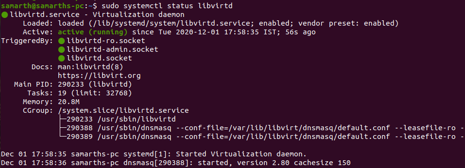
Enable libvirtd to start on boot

sudo systemctl enable --now libvirtd

Creating a Virtual Machine on Ubuntu

There are 2 ways to create a VM, first via command link and second via UI.

Creating a VM using the command line
sudo virt-install --name=samteck-vm --os-variant=Debian10 --vcpu=2 --ram=2048 --graphics spice --location=/home/Downloads/deepin-20Beta-desktop-amd64.iso --network bridge:vibr0

Here we are giving all the specs (CPU, RAM, Network) and location of the ios file in one command and executing it. After running the command the VM installation will start (image at end of the post)

Creating a VM using Graphical Interface

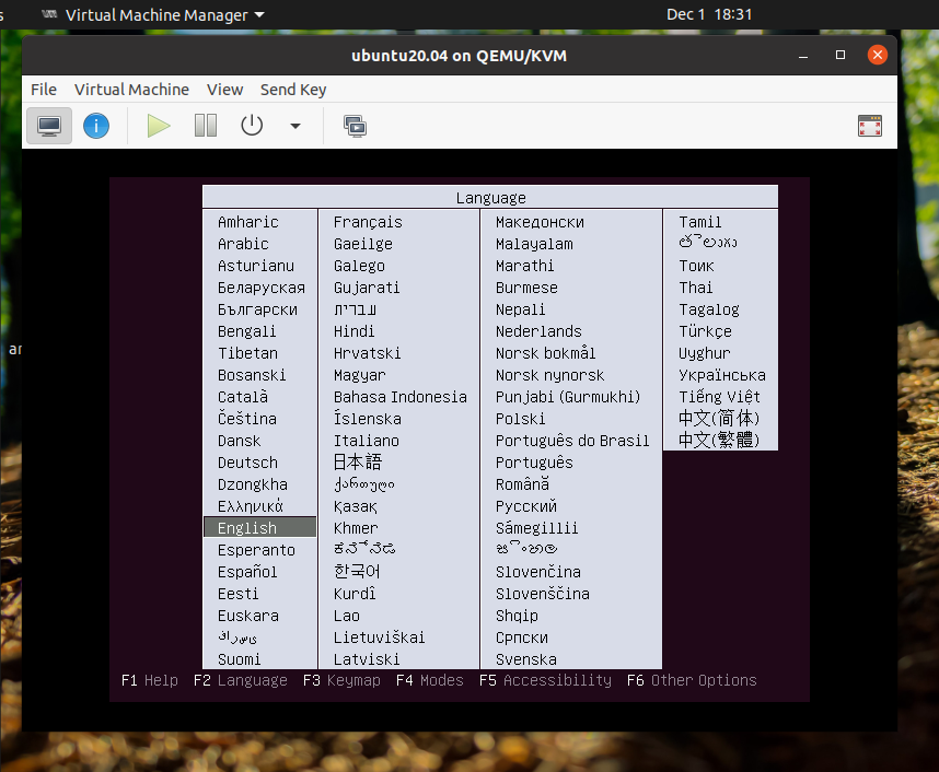
The graphic interface is more or less like other VM offerings where we need to manually select the specifications and the iso file. To start the KVM Graphical interface execute the below command.

virt-manager

After this, a GUI application will open up you can begin by creating a new VM, select the local ISO file, hardware specs, and Network interface. And VM installing process will start as shown in the image below.

ubuntu-kvm

Afterward just continue with the steps as usual ubuntu installation: setting the username, PC-name, password, locale, etc. And after boot up, you need to need to set the screen resolution. Moreover, this VM will be a part of a virtual network virbr0 and will have a NAT IP address.

Now you can use a GUI-based OS interface to access this server or you can just ssh onto it from your host computer. There is another way to put this VM in your actual LAN using Bridge mode thereby your VM getting the IP address directly from your router, which we will discuss in the next post.

How to set up Node-Red on 64bit/32bit Raspberry Pi OS

raspberry-pi-64bit-node-red-

Node-Red has been the go-to use tool for Prototyping IOT projects and the same goes for Raspberry Pi. But till recent times Raspberry Pi OS (RIP Raspbian) was only available in 32bit armhf architecture. However, a 64bit image for Raspberry was released in beta mode and it’s quite stable.

I don’t what took these guys to release a 64bit image so late even though raspberries have been fitted with 64bit processors for quite some time, but better stable than crashing.

raspberry-pi-64bit-node-red-

Download and Flash 64bit Raspberry Pi OS

Here: https://downloads.raspberrypi.org/raspios_arm64/images/raspios_arm64-2020-08-24/

Just follow the usual steps to flash this image onto sd-card via etcher and plug it into Raspberry Pi (just note that this image will run only with RPi-4 and RPi-3)

Setup your Raspberry pi as usual and get ready for the next section of this tutorial.

Installing Node-Red on 64bit Raspberry Pi OS

So installation of Node-Red on 64bit version of Raspberry Pi OS is quite similar to any other version as the package managers will take care of fetching the 64bit version from the mirrors.

– sudo apt-get update

– sudo apt-get dist-upgrade

– curl -sL https://deb.nodesource.com/setup_10.x | sudo -E bash –

– sudo apt-get install -y nodejs

– sudo npm install -g –unsafe-perm node-red

That’s all, now you can run the Node-Red server by typing node-red in your terminal and opening http://localhost:1880 to access the console.

Run the below command to start Node-Red in Background: sudo nohup node-red &

Test Speed of your Internet from Terminal/CLI in Linux

speedtest-terminal

There are various web applications to test the speed of your Internet Connection. The most famous being Speedtest by Ookla – Link Here

But suppose you want to test your network bandwidth from a Linux machine without a desktop environment installed or for just looking cool among your friends.

speedtest-terminal

Follow below steps to install Speedtest app from Terminal

Execute below commands in you terminal window. These commands will add ookla (speedtest) repo mirror to your apt-get package manager list.

    • sudo apt-get install gnupg1 apt-transport-https dirmngr
    • export INSTALL_KEY=379CE192D401AB61
    • sudo apt-key adv --keyserver keyserver.ubuntu.com --recv-keys $INSTALL_KEY
    • echo "deb https://ookla.bintray.com/debian generic main" | sudo tee /etc/apt/sources.list.d/speedtest.list
    • sudo apt-get update
    • sudo apt-get install speedtest

After the installation just run “speedtest” command, it will automatically choose the best server for testing and display the results.

How to Install and Configure SSH Server on a Ubuntu Desktop

ssh-protocol

We usually use SSH to access Cloud Servers or IoT gateways – like Raspberry Pi, but sometimes a situation arises where we need to SSH into our desktop for some or other reasons. Or maybe you want to install SSH Server to a Ubuntu OS for a completely different purpose. That’s fine because here we will discuss how to install and configure SSH Server for your Ubuntu Machine.

You can use this method for any version of Ubuntu, Xubuntu, Lubuntu or any other OS based on Debian. Know more about terms like – LINUX, UNIX, Debian, Ubuntu, Kernel, GNOME, GNU, APT, RPM, YUM, GNOME

ssh-protocol

3 Steps to Install and Configure SSH on Ubuntu via Terminal

  1. Install SSH-Server : sudo apt install openssh-server
  2. After installation the SSH service will start automatically, you can verify it by running sudo systemctl status ssh it will show “active running”. Press “q” to quit
  3. Now you need to enable ssh from firewall by using this command : sudo ufw allow ssh

That’s all now you can connect to your ubuntu machine by using ssh username@host-ip

How to flash ESP8266-01 – Default/Custom Firmware Upgrade

esp8266-firmware-upgrade

We know that ESP8266-01 is an impressive, low cost and powerful module with networking capabilities. But sometimes it becomes a bit tedious task to flash your firmware onto it. So to simplify the whole process and understanding of putting your firmware on ESP8266-01 (by AI-Thinker), we are writing this article.

esp8266-firmware-upgrade
Ai-Thinker Board

The AI-Thinker boards have a black PCB with the words “AI-CloudInside” printed near the PCB antenna. These have a flash memory of 1 Megabyte (aka 8 megabits). The other type by the generic manufacturers might just have 512 KiB flash (and their PCBs could be blue in color).

ESP8266 comes pre-programmed with an AT command set firmware, meaning, you can simply hook this up to your Arduino device and get about as much WiFi-ability as a WiFi Shield offers. This module has a powerful on-board processing and storage capability that allows it to be integrated with the sensors and other applications through its GPIOs.

Hardware Setup

We need below-mentioned hardware components:

  1. ESP8266 (obvious, but still needs a mention)
  2. USB-TTL (learn how to use Arduino as USB-TTL adapter)
  3. Bunch of jumper wires

To put ESP8266 into bootloader mode we need to first pull GPIO-0 to GND. When we restart the module, this setup will put it into bootloader mode.

esp8266-firmware-update-arduino

Software Setup

There are 2 ways to flash your firmware, the First one is using esptool which is a bit complicated process and the second one is using Arduino IDE which also uses esptool at backend abstracting all its complexities.

1. Arduino Method

The Arduino method is only flashing the user-written firmware. For flashing official firmware head on to next method

  • Start the Arduino IDE
  • Go to File > Preferences
  • Add the below-given link to Additional Boards Manager URLs https://arduino.esp8266.com/stable/package_esp8266com_index.json
  • Go to Tools > Boards > Boards Manager…
  • Search ESP8266
  • Click the Install button to install the ESP8266 Board
  • Now close the Boards Manager window and select the Generic ESP8266 Module from the board selection list
  • The installation of ESP8266 in Arduino IDE is done.

Now select the correct serial port and choose the Blink example. After that press upload button as usual and your firmware will be flashed. After this, you can restart the ESP8266 after removing GPIO-0 from GND.

2. Using Esptool from the terminal (command line)

This the default tool which is provided by Espressif to flash firmware onto ESP chips. This requires some understanding of terminal and any wrong step here may brick your module.

Download Official Firmware

The latest firmware at the time of writing this was 1.7.3 and as you can see from the description on the download page, that only supported a 1024 + 1024 KiB flash map. ie, You need 2 MB of flash space on your board. The ESP-01 by Ai Thinker only had 1 MB in total. So I had to go with the older 1.6.2 that supported a 512 KiB + 512 KiB map.

Download your preferred firmware zip file, extract the zip file and navigate to ./bin/at/


Next, Install the esptool.py python module.

git clone https://github.com/espressif/esptool

Over at ./bin/at/, You should find a README.md that will show you the offsets of where each bin file is supposed to be flashed. We’ll be flashing in the boot mode (GPIO-0 to Gnd). While flashing with official firmware there are 4 files needs to be flashed. The first one being the program and the rest 3 are related to bootloader and partition tables.

esptool.py –port /dev/tty.usbserial-FTG54BPS –baud 115200 write_flash –flash_mode dio 0x00000 boot_v1.2.bin
esptool.py –port /dev/tty.usbserial-FTG54BPS –baud 115200 write_flash –flash_mode dio 0x01000 at/512+512/user1.1024.new.2.bin
esptool.py –port /dev/tty.usbserial-FTG54BPS –baud 115200 write_flash –flash_mode dio 0x7C000 esp_init_data_default_v05.bin
esptool.py –port /dev/tty.usbserial-FTG54BPS –baud 115200 write_flash –flash_mode dio 0x7E000 blank.bin

Now you are good to go. Just remove the GPIO-0 and reboot the ESP board. Type the command ‘AT+GMR’ and you will get the firmware version in return.

You can also use ESP Flasher Tool, but sadly is it’s only available for Windows platform.

How ESP8266-01 works : Pinout and Connecting to Arduino

ESP-8266-pinout

EspressIf has been making various IoT chips at an extremely low cost, one such chip is ESP8266. There are various modules of this chip and here we will talk about on such module by Ai-Thinker: ESP8266-01. Also, there are 2 variants of ESP8266-01: blue(512KB flash) and black(1MB flash)

esp8266-01-blue-black

The ESP8266 is a microcontroller chip from Chinese manufacturer Espressif, built around a Tensilica Xtensa LX3 processor, it includes onboard Wi-Fi. Originally intended to be used as UART to WiFi adaptor, allowing other micro-controllers to connect to a Wi-Fi network and make simple TCP/IP connections using Hayes-style (AT) commands, the ESP8266 quickly became popular as a stand-alone micro-controller because of its low price point.

Although the ESP8266 chip is made by Espressif, modules bearing the chip come from a variety of different manufacturers.

ESP8266-01 PIN OUT and Configuration

ESP-8266-pinout

Pin Number Pin Name Alternate Name Normally used for Alternate purpose
1 Ground Connected to the ground of the circuit
2 TX GPIO – 1 Connected to Rx pin of programmer/uC  to upload program Can act as a General purpose Input/output pin when not used as TX
3 GPIO-2 General purpose Input/output pin
4 CH_EN Chip Enable – Active high
5 GPIO – 0 Flash General purpose Input/output pin Takes module into serial programming when held low during start up
6 Reset Resets the module
7 RX GPIO – 3 General purpose Input/output pin Can act as a General purpose Input/output pin when not used as RX
8 Vcc Connect to +3.3V only

Also, I always prefer to make a guided jumper wires connector for easy working with ESP module.

esp-jumper-connector

Make connection with Arduino

Esp8266-01 comes with AT-commands default firmware there are 2 ways we can interact with that firmware via Arduino.

List of important AT commands.

1.Using Arduino as Host MCU to communicate with ESP8266

Using the Software Serial library we can send serial commands to Arduino and Arduino with again send it to ESP8266 and vice versa. Code Below

#include <SoftwareSerial.h>

SoftwareSerial mySerial(10, 11); // RX, TX

void setup() {
// Open serial communications and wait for port to open:
Serial.begin(57600);
while (!Serial) {
; // wait for serial port to connect. Needed for native USB port only
}

Serial.println(“Goodnight moon!”);

// set the data rate for the SoftwareSerial port
mySerial.begin(4800);
mySerial.println(“Hello, world?”);
}

void loop() { // run over and over
if (mySerial.available()) {
Serial.write(mySerial.read());
}
if (Serial.available()) {
mySerial.write(Serial.read());
}
}


2. Using Arduino As USB-TTL by bypassing ATmega MCU

Arduino can be used as a USB-TTL converter and we can directly send out commands to ESP8266.

Click here to learn how to use Arduino as USB-TTL converter.

What are ESP32, ESP8266 Modules and Development Board

ESP32_chip_ic

One of the major factors which contributed towards the massive explosion of IoT devices in our day to day life is cheap Silicon. There are so many silicon manufactures that are providing highly capable MCU’s for fraction of the cost. One such manufacturer is EspressIf which makes 2 very famous chips with networking capabilities: ESP8266 & ESP32 (photos below).

ESP8266EX-Chip-ICESP32_chip_ic


Mind you, these chips are embedded onto the modules with which most people are familiar. Have a look at the ESP32 module below. These modules go on top of the IoT PCB which we design. Moreover, these modules can be used as MCU+Network_IC (Hostless) or as Network_IC and external MCU (Hosted).

esp32-wroom-32-module


Also, there are Development boards/kits available in the market (image below) which are used to prototyping and learning about these boards. They provide an easy development environment and various debugging features which helps to come up with the binary code(firmware), which goes onto the ESP Module.

ESP32-developer-kit

ESP 8266 Specifications

  • Tensilica Xtensa LX106 32 bit RISC CPU running at 80 MHz
  • On-board Wi-Fi (2.4 GHz)
  • Integrated 10 bit analog to digital converter
  • SDIO 2.0, (H) SPI, UART, I2C, I2S, IR Remote Control, PWM, GPIO
  • 16 GPIO Pins
  • UART – 2x TX and 1x RX
  • Operating Voltage : 3.0 ~ 3.6V
  • Average Operating Current: 80mA
  • Operating Temperature : -40°C ~ 125°C
  • Frequency Range : 2400 ~ 2483.5MHz

ESP 32 Specifications

  • Tensilica Xtensa LX6 microprocessor @ 160 or 240 MHz
  • On-Board Wi-Fi and Bluetooth
  • ADCs, DACs, I²C, UART, CAN 2.0, SPI, I²S, RMII, PWM

Head onto this amazing article on Difference b/w ESP32 & ESP8266

AT Commands for ESP8266: Where and How to use them

At_COMMAND

The Hayes command set or AT commands are instructions used to control a modem, but the default firmware of ESP8266 also allows us to use AT commands to communicate with ESP8266.

AT is the abbreviation of Attention. Every command line starts with “AT” or “at”. Note that the starting “AT” is the prefix that informs the modem about the start of a command line. It is not part of the AT command name. For example, +GMR is the actual AT command name in AT+GMR. However, some people and web sites use them interchangeably as the name of an AT command.

At_COMMAND

Here is a list of AT commands which you can use to communicate with ESP8266 (you can send these commands via Arduino/MCU to drive ESP8266). There are two types of AT commands – basic commands(commands that do not start with “+”) and extended commands(commands that start with “+”).

Basic commands are AT commands that do not start with “+”. For example, D (Dial), A (Answer), H (Hook control) and O (Return to online data state) are basic commands. Rest are extended commands explained below :

Commands Description Set/Execute Parameters
AT+RST restart the module
AT+CWMODE wifi mode AT+CWMODE=<mode> 1= Sta, 2= AP, 3=both
AT+CWJAP join the AP AT+ CWJAP =<ssid>,< pwd > ssid = ssid, pwd = wifi password
AT+CWLAP list the AP AT+CWLAP
AT+CWQAP quit the AP AT+CWQAP
AT+ CWSAP set the parameters of AP AT+ CWSAP= <ssid>,<pwd>,<chl>, <ecn> ssid, pwd, chl = channel, ecn = encryption
AT+ CIPSTATUS get the connection status AT+ CIPSTATUS
AT+CIPSTART set up TCP or UDP connection 1)single connection (+CIPMUX=0) AT+CIPSTART= <type>,<addr>,<port>; 2) multiple connection (+CIPMUX=1) AT+CIPSTART= <id><type>,<addr>, <port> id = 0-4, type = TCP/UDP, addr = IP address, port= port
AT+CIPSEND send data 1)single connection(+CIPMUX=0) AT+CIPSEND=<length>; 2) multiple connection (+CIPMUX=1) AT+CIPSEND= <id>,<length>
AT+CIPCLOSE close TCP or UDP connection AT+CIPCLOSE=<id> or AT+CIPCLOSE
AT+CIFSR Get IP address AT+CIFSR
AT+ CIPMUX set mutiple connection AT+ CIPMUX=<mode> 0 for single connection 1 for mutiple connection
AT+ CIPSERVER set as server AT+ CIPSERVER= <mode>[,<port> ] mode 0 to close server mode, mode 1 to open; port = port
+IPD received data

A brief list of AT commands can be found HERE

Comprehensive list of AT commands can be found HERE

Configure Visual Studio code for Arduino Development

Configure Visual Studio code for Arduino Development

These days IoT is becoming such a buzz word that many software professionals want to dive into the Embedded world. And the primitive board to start with embedded programming is ARDUINO. But the IDE which Arduino foundation provides us is basic and lacks essentials features for serious programming like Intellisense, GIT integration, code lay-outing, and necessary shortcuts.

One of the best IDE providers in the marketplace “VS Code” released an Arduino plugin to make life easier for serious programmers who want to work on Arduino. So here in this article, we will see how to install and configure VS Code for Arduino development.

Just follow the below steps and you will be up and running with a ‘Hello World’ example or Blink as they call it in Arduino world.

1. Install VS Code

Head on to https://code.visualstudio.com/download

2. Install Arduino IDE

Don’t get confused, official Arduino IDE contains some important libraries which will be used by VS Code.

Download Arduino IDE: https://www.arduino.cc/en/main/software

3. Install Arduino Extension for VS Code

Install Arduino extension for VS Code: https://marketplace.visualstudio.com/items?itemName=vsciot-vscode.vscode-arduino

This extension will also install C/C++ package as an add-on which is important for this setup.

After installing these IDE and Packages close them. Connect the Arduino board and re-launch VS Code.

4. Open Blink Example for Arduino

Not all VS Code’s functionality is accessible via menus. Instead, VS Code has a command-line-type facility for interfacing with extensions called the Command Palette.

To run the Command Palette, type “Cntrl+Shift+p” to display a drop-down box that you can enter commands in. Type “Arduino Examples” into the command palette and press return. This will open up a link to the familiar example projects – navigate to “01.Basics” and then double click on “Blink” to open the world-famous Blink project.

Once you have opened up an Arduino .ino file, VS Code reconfigures in an Arduino mode, and gives access to special functionality in its bottom blue margin, as shown in the image below.

VS-code-arduino-config

Click on <Select Programmer> and select AVR ISP (Arduino AVR Board)

Click on <Select Board Type> and select Arduino/Genuino Uno

Click on <COM> and select your Arduino serial port

At the top right of the window, you will see icons for Verify and Upload the code. All other features from Arduino IDE can be searched on Command Pallet

5. Taking Advantage of VS Code functionalities

  • Intellisense and Error Checking: IntelliSense is a code completion engine that looks through all of the source code in your project — including external libraries — and then suggests functions and variables as you type your code. Also, VS Code constantly checks your code as you write. If it detects an error, it underlines it with a red squiggle and offers advice.
  • Use a src folder to hold your code folders: Layout your project properly using a folder structure as below:-

ArduinoRootFolder
— src
——- FolderA
——- FolderB
————-SubfolderA

  • Add an ‘output’ option to arduino.json: By default, you will have an arduino.json file in your project under .vscode folder which contains build information for your project. Just add the below line to build your project in the current folder itself

,”output”: “build”

  • Gitify Your project: One powerful thing which you can do VS Code is using GIT and checking in your code without any delay. Just click the Git icon at the extreme left of the window.

That’s all you need to set up your Arduino project in a professional way. Below are some links which you can refer to if you want a more elaborative explanation.

  1. Basic Guide
  2. Advance Guide
  3. Full Comprehensive Guide

Enable SSH in Raspbian/Ubuntu without Keyboard & Monitor

ssh-into-raspberry-pi

Many times, a situation arises for an IOT developer where he/she wants to ssh onto a newly flashed raspberry pi running on Ubuntu/Raspbain but without a Monitor and keyboard or any other input device.

ssh-into-raspberry-pi

The first and foremost thing to SSH into a pi is to open port 22. But its always closed for security purposes. When we have a pi with a keyboard and monitor its easy to open the port but that isn’t the case always. Here we will explain how to open port 22 and enable ssh without any input device.

Open Port 22 in Raspbian/Ubuntu for SSH

Without wasting time we will straight tell you to steps to open port 22

  1. Prepare your sd card using Etcher and your OS image (or Mount flashed SD card)
  2. Navigate to the SD card [boot] using your OS file manager or terminal
  3. Create a new empty file named ssh, without any extension, inside the boot directory [touch /boot/ssh]
  4. Remove the SD card from your computer and put it in your Raspberry Pi.
  5. Power on your Pi board. On boot Pi will check whether this file exists and if it does, SSH will be enabled and the file is removed.

That’s it, now connect your raspberry pi to your network via LAN, find the IP address from your Router’s console and ssh onto it. If you want to SSH to your Pi from a different network – Click Here.